EasyManua.ls Logo

Sony HCD-EH15 Service Manual

Sony HCD-EH15
40 pages
To Next Page IconTo Next Page
Page #1 background imageLoading...
Page #1 background image
SERVICE MANUAL
Sony Corporation
Audio Business Group
Published by Sony Techno Create Corporation
HCD-EH15
SPECIFICATIONS
COMPACT DISC DECK RECEIVER
9-889-094-01
2008D05-1
©
2008.04
Canadian Model
UK Model
E Model
Australian Model
Russian Model
Ver. 1.0 2008.04
HCD-EH15 is the ampli er, CD player, tape
deck and tuner section in CMT-EH15.
CD
Section
Model Name Using Similar Mechanism
NEW
Base Unit Name
BU-K8BD90-WOD
Optical Pick-up Name
KSM-213CDP
Tape
Section
Model Name Using Similar Mechanism
NEW
Tape Transport Mechanism Type
MF-EH10
Amplifier section
European and Russian models:
DIN power output (rated): 4 + 4 W (4 ohms at 1 kHz, DIN)
Continuous RMS power output (reference): 5 + 5 W (4 ohms at 1 kHz,
10% THD)
Music power output (reference): 7 + 7 W
Other models:
DIN power output (rated): 4 + 4 W (4 ohms at 1 kHz, DIN)
Continuous RMS power output (reference): 5 + 5 W (4 ohms at 1 kHz,
10% THD)
Inputs
AUDIO IN (stereo mini jack): Sensitivity 800 mV, impedance 47 kilohms
Outputs
PHONES (stereo mini jack): Accepts headphones with an impedance of
8 ohms or more
SPEAKER: Accepts impedance of 4 ohms
CD player section
System: Compact disc and digital audio system
Laser Diode Properties
Emission Duration: Continuous
Laser Output*: Less than 44.6μW
* is output is the value measurement at a distance of 200 mm from the
objective lens surface on the Optical Pick-up Block with 7 mm aperture.
Frequency response: 20 Hz
20 kHz
Signal-to-noise ratio: More than 90 dB
Dynamic range: More than 90 dB
Tape deck section
Recording system: 4-track 2-channel, stereo
Tuner section
FM stereo, FM/AM superheterodyne tuner
Antenna:
FM lead antenna
AM loop antenna
FM tuner section:
Tuning range
Canadian model: 87.5 108.0 MHz (100 kHz step)
Other models: 87.5 108.0 MHz (50 kHz step)
Intermediate frequency: 10.7 MHz
AM tuner section:
Tuning range
Canadian and Latin American models:
530 1,710 kHz (with 10 kHz tuning interval)
531 1,710 kHz (with 9 kHz tuning interval)
European and Russian models:
531 1,602 kHz (with 9 kHz tuning interval)
Australian model:
531 1,710 kHz (with 9 kHz tuning interval)
530 1,710 kHz (with 10 kHz tuning interval)
Other models:
531 1,602 kHz (with 9 kHz tuning interval)
530 1,610 kHz (with 10 kHz tuning interval)
Intermediate frequency: 450 kHz
General
Power requirements:
Canadian model: AC 120 V, 60 Hz
Eu
Mexican model: AC 120 V, 60 Hz
ropean and Russian models: AC 230 V, 50/60 Hz
Australian model: AC 230 240 V, 50/60 Hz
Argentine model: AC 220 V, 50/60 Hz
Korean model: AC 220 V, 60 Hz
Taiwan model: AC 120 V, 50/60 Hz
Other models: AC 110 120 or 220 240 V, 50/60 Hz
Adjustable with voltage selector
Power consumption: 25 W
Dimensions (w/h/d) (excl. speakers): Approx. 155 × 241 × 224.6 mm
Mass (excl. speakers): Approx. 2.2 kg
Design and specications are subject to change without notice.
Question and Answer IconNeed help?

Do you have a question about the Sony HCD-EH15 and is the answer not in the manual?
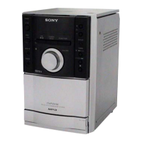
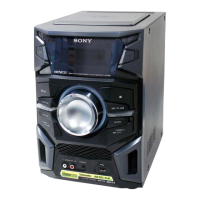
Sony HCD-EH15 Specifications

General IconGeneral
TypeMini Hi-Fi Component System
Disc PlaybackCD, CD-R/RW
TunerFM/AM
BluetoothNo
USB PlaybackNo
Cassette DeckYes
Speaker Configuration2.0 Channel
Power Output100W (50W x 2)

Summary

SPECIFICATIONS

Amplifier Section

Electrical and output specifications for the amplifier.

CD Player Section

Specifications for the CD playback system.

Tuner Section

Specifications for FM/AM radio reception.

SECTION 2 GENERAL

Basic Operations

Instructions for using the system's primary functions.

Before Using the System

Initial setup for remote and clock.

Other Operations

Advanced functions like programming and timers.

SECTION 1 SERVICING NOTES

Handling Optical Pick-up Block

Precautions for servicing the optical pick-up and base unit.

Laser Diode Emission Check

Method for checking laser diode emission and safety.

SECTION 3 DISASSEMBLY

3-1. Disassembly Flow

Overview of the disassembly sequence.

3-2. Rear Cabinet Block

Procedure for removing the rear cabinet.

3-3. Front Cabinet Block, Top Cabinet Block, Main Board

Disassembly of front, top, and main board components.

3-4. MF-EH10 (Tape Mechanism Deck), Cassette Lid

Disassembly of the tape deck and cassette lid.

3-5. Base Unit Block (BU-K8BD90-WOD)

Disassembly of the base unit containing the CD mechanism.

3-6. Optical Pick-up Block (KSM-213CDP)

Disassembly and replacement of the optical pick-up.

SECTION 4 TEST MODE

Cold Reset Procedure

Resets the system to factory default settings.

Panel Test Mode

Checks the functionality of all panel buttons and displays.

CD Service Mode

Controls SLED movement and laser power for CD service.

SECTION 5 MECHANICAL ADJUSTMENTS

Precautions for Adjustment

General safety and handling guidelines for adjustments.

Torque Measurement

Procedures for measuring tape deck motor torques.

SECTION 6 ELECTRICAL ADJUSTMENTS

Head Azimuth Adjustment

Procedure for aligning the record/playback head for optimal sound.

AM Voltage and Tracking Adjustment

Adjustments for AM tuner voltage and tracking.

FM Detector Adjustment

Procedure for adjusting the FM detector for best performance.

Focus Bias Check

Procedure for checking CD player focus bias using an oscilloscope.

SECTION 7 DIAGRAMS

Printed Wiring Board Notes

Guidelines for interpreting printed wiring board diagrams.

Schematic Diagram Notes

Guidelines for interpreting schematic diagrams.

7-1. Printed Wiring Board - CD Board

Layout of the CD board's printed wiring.

7-2. Schematic Diagram - CD Board

Schematic representation of the CD board circuitry.

7-3. Printed Wiring Board - PANEL Board

Layout of the panel board's printed wiring.

7-4. Schematic Diagram - PANEL Board

Schematic representation of the panel board circuitry.

7-5. Schematic Diagram - MAIN Section (1/2)

Part one of the main board schematic.

7-6. Schematic Diagram - MAIN Section (2/2)

Part two of the main board schematic.

7-7. Printed Wiring Boards - MAIN Section

Layout of the main board's printed wiring.

IC Block Diagrams

Block diagrams illustrating the internal functions of key ICs.

CD Board IC Pin Function Description

Detailed pinout and function for CD board IC101.

SECTION 8 EXPLODED VIEWS

8-1. Overall Section

Exploded view of the complete unit assembly.

8-2. Front Cabinet Section

Exploded view of the front panel components.

8-3. Top Cabinet Section

Exploded view of the top cabinet and CD mechanism.

8-4. Base Unit Section (BU-K8BD90-WOD)

Exploded view of the base unit and its components.

SECTION 9 ELECTRICAL PARTS LIST

CD Board Parts

List of electrical components for the CD board.

Main Board Resistors

List of resistors used on the main board.

Main Board Capacitors

List of capacitors used on the main board.

Main Board Diodes and Connectors

List of diodes and connectors on the main board.

Panel Board Resistors

List of resistors used on the panel board.

Panel Board Switches

List of switches on the panel board.

Accessories

List of included accessories like power cords and adapters.

REVISION HISTORY

Related product manuals