23
HCD-GN700/GX8800
RFAC Level Check
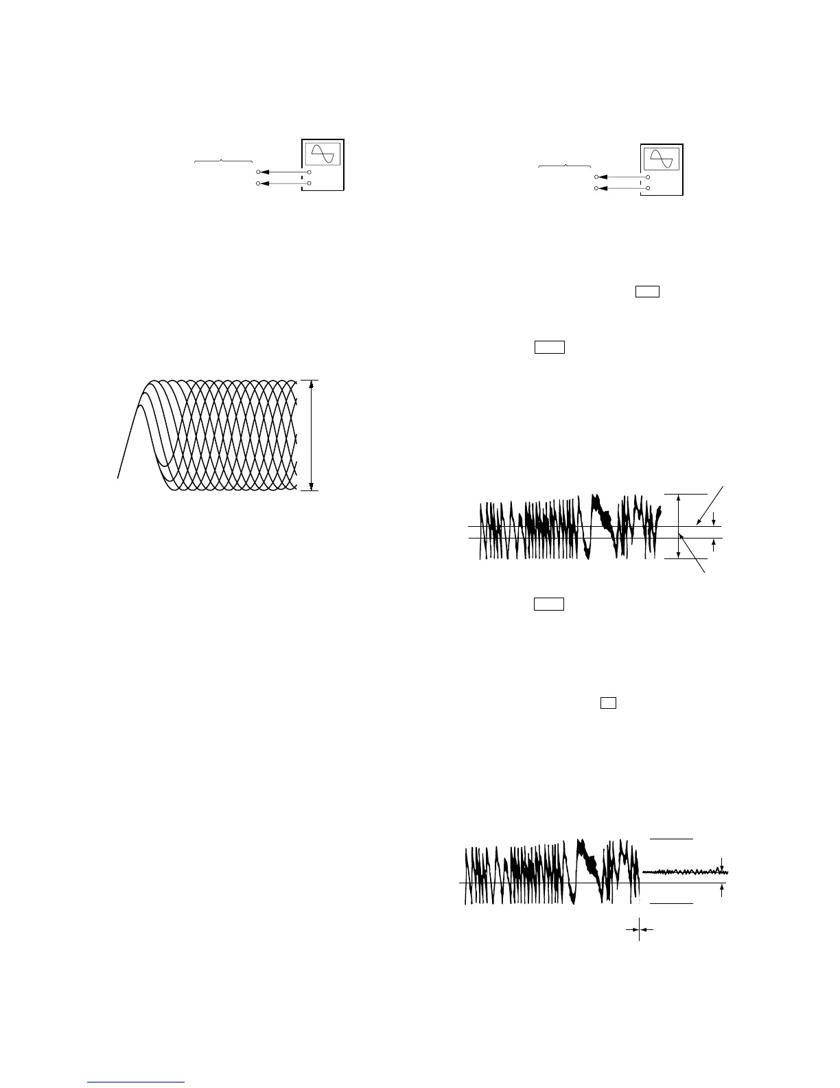
Connection:
Procedure:
1. Connect an oscilloscope to test point TP5 (RFAC) and TP
7(DVC) on the CD board.
2. Turn the power on.
3. Put the disc (YEDS-18) in to playback the number five track.
4. Confirm that oscilloscope waveform is clear and check RFAC
signal level is correct or not.
Note: A clear RFAC signal waveform means that the shape “◊” can be
clearly distinguished at the center of the waveform.
RFAC signal waveform
Checking Location: CD board (SIDE B)
(See page 24.)
E-F Balance Check
Connection:
Procedure:
1. Connect an oscilloscpe to test point TP2 (TE) and TP7 (DVC)
on the CD board.
2. Turn the power on.
3. Select the function “CD”.
4. Press three buttons of
[ENTER], M , and
[SURRUUND MODE] simultaneously to set the CD service
mode.
5. Put the disc (YEDS-18) in to playback the number five track.
6. Press the . button. The message “TRAVERSE” is
displayed. (The tracking servo and the sledding servo are turned
OFF)
7. Check the level B of the oscilliscope's waveform and the A
(DC voltage) of the center of the Traverse waveform.
Confirm the following :
A/B x 100 = less than ± 22%
Traverse Waveform
8. Press the . button. The message “TRAVERSE” is
displayed. (The tracking servo and sledding servo are turned
ON)
Confirm the C (DC voltage) is almost equal to the A (DC
voltage) is step 5.
9. To exit from this mode, perform as follows.
1) Move the optical pick-up to the most inside track.
2) Press three buttons of x , [CLEAR], and [DISPLAY]
simultaneously. (cold reset)
Notes: • Always move the optical pick-up to most inside track when
exiting from this mode. Otherwise, a disc will not be unloaded.
• Do not run the sled motor excessively, otherwise the gear can
be chipped.
Traverse Waveform
Checking Location: CD board (SIDE B) (See page 24.)
+
–
CD board
TP5 (RFAC)
TP7 (DVC)
oscilloscope
VOLT/DIV: 200 mV
TIME/DIV: 500 ns
level: 0.9
±
0.4 Vp-p
+
–
CD board
TP2 (TE)
TP7 (DVC)
oscilloscope
0V
B
level: 1.0
±
0.5 Vp-p
Center of
the waveform
A (DC
voltage)
0V
Tracking servo
Sled servo
ON
C (DC
voltage)
Tracking servo
Sled servo
OFF