56
HCD-RV22/RV55
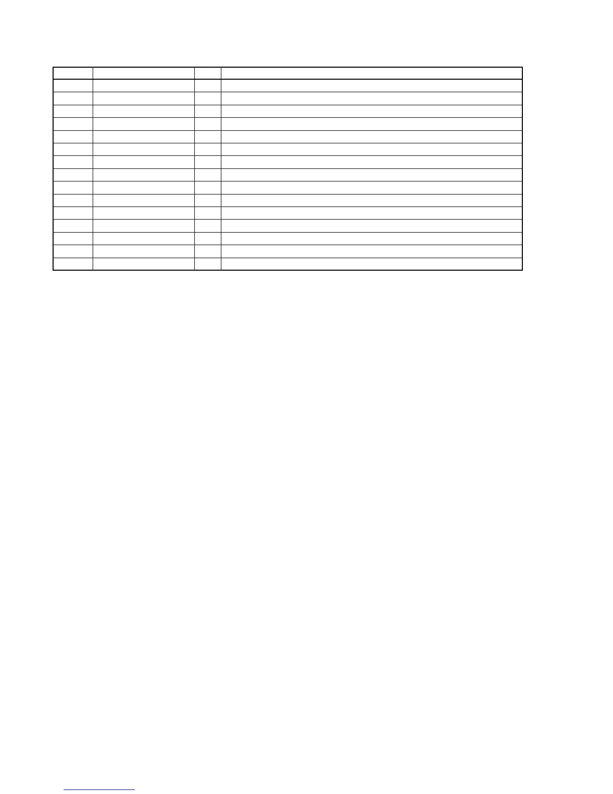
Pin No. Pin Name I/O Pin Description
202 AUDDTO1 O Serial audio data output Not used. (Open)
203 AUDBCK O Serial audio bit clock signal (2.8224 MHz) output to the digital filter
204 AUDLRCK O Serial audio L/R sampling clock signal (44.1 kHz) output to the digital filter
205 AUDXCLKO O Serial audio clock signal output to the digital filter
206 CLKA I Sub system clock input (27 MHz)
207 CLKB O Sub system clock output (27 MHz)
208 VDD9 — Digital power supply pin (+2.5 V) (for CD-DSP block)
209 THRCLK I Clock signal input for the test Not used. (Open)
210 TESTEN I Setting pin for the test Normally : fixed at “L”
211 TCLK I Clock signal input for the test Not used. (Fixd at “L”)
212 TMODE1 I Selection signal input for the test Not used. (Fixd at “L”)
213 TRST I Reset signal input for the test Not sused. (Open)
214 VSS9 — Digital ground pin
215 NC — Not used. (Fixd at “L”.)
216 V AVD1 — Analog power supply pin (+2.5 V) (for D/A converter)


 To Next Page