HCD-SH2000
6
Note: Follow the disassembly procedure in the numerical order given.
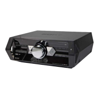
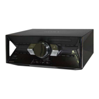
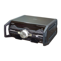
2-1. SIDE PANEL A, SIDE PANEL B AND TOP PANEL SECTION
9 top panel section
7 three
screws
(+BVTP 3
x
10)
1 four
screws
(3.5 x 16)
4 four
screws
(3.5 x 16)
2
8
5
3
side panel A
6
side panel B
Note: Disassemble the unit in the order as shown below.
2-1. SIDE PANEL A,SIDE PANEL B
AND TOP PANEL SECTION
(Page 6)
2-2. BACK PANEL SECTION
(Page 7)
SET
2-3. FRONT PANEL SECTION
(Page 7)
2-4. DMB21 BOARD
(Page 8)
2-5. CDM SECTION
(Page 8)
2-6. CD MECHANISM DECK BLOCK (1)
(Page 9)
2-8. DAMP Board, MAIN Board
(Page 10)
2-7. CD MECHANISM DECK BLOCK (2)
(Page 9)
2-9. SWITCHING REGULATOR
(Page 10)
SECTION 2
DISASSEMBLY