EasyManua.ls Logo

Sony HCD-SHAKE7 Service Manual

Sony HCD-SHAKE7
92 pages
To Next Page IconTo Next Page
Page #1 background imageLoading...
Page #1 background image
SERVICE MANUAL
Sony Corporation
Published by Sony EMCS (Malaysia) PG Tec
HCD-SHAKE7
MINI HI-FI COMPONENT SYSTEM
9-890-619-03
2013K80-1
©
2013.11
E Model
Ver. 1.2 2013.11
HCD-SHAKE7 is the tuner, USB, CD player, Bluetooth, NFC
and ampli er section in SHAKE-7.
SPECIFICATIONS
CD Section
Model Name Using Similar Mechanism NEW
CD Mechanism Type CDM90-DVBU202//M
Optical Pick-up Name CMS-S76RFS7G
Ampli er section
The following are measured at
Mexican model:
AC 120 V – 240 V, 60 Hz
Other models:
AC 120 V – 240 V, 50/60 Hz
Tweeters/woofers
Power Output (rated):
320 W + 320 W (at 4 ohms, 1 kHz,
1% THD)
RMS output power (reference):
520 W + 520 W (per channel at
4 ohms, 1 kHz)
Mid speakers
Power Output (rated):
240 W + 240 W (at 5 ohms, 1 kHz,
1% THD)
RMS output power (reference):
385 W + 385 W (per channel at
5 ohms, 1 kHz)
Subwoofers
Power Output (rated):
320 W + 320 W (at 4 ohms, 100 Hz,
1% THD)
RMS output power (reference):
520 W + 520 W (per channel at
4 ohms, 100 Hz)
Inputs
TV/DVD/SAT (AUDIO IN) L/R
Voltage 2 V, impedance 47 kilohms
PC/GAME (AUDIO IN) L/R
Voltage 2 V, impedance 47 kilohms
MIC
Sensitivity 1 mV, impedance 10 kilohms
A (USB), B (USB) port: Type A
USB section
Supported bit rate
WMA:
48 kbps – 192 kbps, VBR, CBR
AAC:
48 kbps – 320 kbps, VBR, CBR
Sampling frequencies
WMA: 44.1 kHz
AAC: 44.1 kHz
Supported USB device
Mass Storage Class
Maximum current
500 mA
Disc/USB section
Supported bit rate
MPEG1 Layer-3:
32 kbps – 320 kbps, VBR
MPEG2 Layer-3:
8 kbps – 160 kbps, VBR
MPEG1 Layer-2:
32 kbps – 384 kbps, VBR
Sampling frequencies
MPEG1 Layer-3:
32 kHz/44.1 kHz/48 kHz
MPEG2 Layer-3:
16 kHz/22.05 kHz/24 kHz
MPEG1 Layer-2:
32 kHz/44.1 kHz/48 kHz
Disc player section
System
Compact disc and digital audio system
Laser Diode Properties
Emission Duration: Continuous
Laser Output*: Less than 44.6 µW
* This output is the value
measurement at a distance of
200 mm from the objective lens
surface on the Optical Pick-up
Block with 7 mm aperture.
Frequency response
20 Hz – 20 kHz
Signal-to-noise ratio
More than 90 dB
Dynamic range
More than 88 dB
Tuner section
FM stereo, FM/AM superheterodyne tuner
Antenna:
FM lead antenna
AM loop antenna
FM tuner section
Tuning range
87.5 MHz – 108.0 MHz
(50 kHz step)
AM tuner section
Tuning range
Pan American models:
531 kHz – 1,710 kHz (9 kHz step)
530 kHz – 1,710 kHz (10 kHz step)
Saudi Arabian model:
531 kHz – 1,602 kHz (9 kHz step)
Other models:
531 kHz – 1,602 kHz (9 kHz step)
530 kHz – 1,610 kHz (10 kHz step)
Bluetooth section
Communication system
Bluetooth Standard version 3.0 +
EDR (Enhanced Date Rate)
Output
Bluetooth Standard Power Class 2
Maximum communication range
Line of sight approx. 10m
1)
Frequency band
2.4 GHz band (2.4000 GHz – 2.4835 GHz)
Modulation method
FHSS (Freq Hopping Spread Spectrum)
Compatible Bluetooth profiles
2)
A2DP (Advanced Audio Distribution
Profile)
AVRCP 1.3 (Audio Video Remote
Control Profile)
Supported codecs
SBC (Sub Band Codec)
AAC (Advanced Audio Coding)
1)
The actual range will vary depending on
factors such as obstacles between devices,
magnetic fields around a microwave oven,
static electricity, reception sensitivity,
antenna’s performance, operating system,
software application, etc.
2)
Bluetooth standard profiles indicate the
purpose of Bluetooth communication
between devices.
General
Power requirements
Mexican model:
AC 120 V – 240 V, 60 Hz
Other models:
AC 120 V – 240 V, 50/60 Hz
Power consumption
420 W
Dimensions (w/h/d) (excl. speakers)
(Approx.) (Except AR)
500 mm × 220 mm × 380 mm
Dimensions (w/h/d) (excl. speakers) (AR)
500 mm × 220 mm × 380 mm
Mass (excl. speakers) (Approx.) (Except AR)
8.4 kg
Mass (excl. speakers) (AR)
8.4 kg
Supplied accessories
Remote control (1)
R6 (Size AA) batteries (2)
FM lead/AM loop antenna (1)
Design and specifications are subject to
change without notice.
License and Trademark Notice
“WALKMAN” and “WALKMAN” logo
are registered trademarks of Sony Corpo-
ration.
MPEG Layer-3 audio coding technology
and patents licensed from Fraunhofer IIS
and Thomson.
Windows Media is either a registered
trademark or trademark of Microsoft
Corporation in the United States and/or
other countries.
This product is protected by certain
intellectual property rights of Microsoft
Corporation. Use or distribution of
such technology outside of this product
is prohibited without a license from
Microsoft or an authorized Microsoft
subsidiary.
• The Bluetooth® word mark and logos are
registered trademarks owned by Bluetooth
SIG, Inc. and any use of such marks by
Sony Corporation is under license. Other
trademarks and trade names are those of
their respective owners.
The N Mark is a trademark or registered
trademark of NFC Forum, Inc. in the
United States and in other countries.
Android is a trademark of Google Inc.
All other trademarks and registered
trademarks are of their respective holders.
In this manual, ™ and ® marks are not
specified.

Table of Contents

Question and Answer IconNeed help?

Do you have a question about the Sony HCD-SHAKE7 and is the answer not in the manual?

Sony HCD-SHAKE7 Specifications

General IconGeneral
Total Power Output (PMPO)1000 W
Audio Output Channels2.0 channels
Number of Discs1
USB PlaybackYes
BluetoothYes
NFCYes
CD PlayerYes
FM RadioYes
Radio TunerFM
Audio Line-inYes
TweeterYes
WooferYes
EqualizerYes
KaraokeYes
Remote ControlYes
Power Output1000 W
Speaker Type2-way
Playable File TypesMP3, WMA

Summary

Specifications Overview

Amplifier, Disc, Tuner, Bluetooth Specs

Details amplifier output, disc/USB formats, tuner ranges, and Bluetooth features.

General Unit Specifications

Covers power requirements, consumption, dimensions, mass, and supplied accessories.

Critical Safety Procedures

AC Leakage Testing Methods

Describes three methods for measuring AC leakage current on exposed metal parts.

Servicing Notes and Precautions

Component Handling and Safety

Guidelines for chip components, flexible circuits, unleaded solder, and laser diodes.

Model Identification and Replacement Notes

Information on model variations and specific component replacement instructions.

Wireless Connectivity Guide

Bluetooth and NFC Device Operations

Instructions for pairing Bluetooth devices, NFC connection, and music playback.

Unit Disassembly Procedures

Panel and Mechanism Component Removal

Step-by-step guides for removing exterior panels and internal mechanisms.

Motherboard and Optical Device Removal

Procedures for removing the motherboard and optical pick-up assembly.

Diagnostic and Test Modes

Panel Test and Model Write Modes

Procedures for entering Panel Test Mode and Model & Destination Write Mode.

System Reset and Special Modes

System Reset and CD Modes Procedures

Instructions for user reset, cold reset, CD ship mode, and aging modes.

Tray Lock, Aging, and History Modes

Procedures for CD tray lock, CDM aging, and history data access modes.

Troubleshooting Protection Modes

Protect Kind Check Test Mode Details

Details on identifying and understanding protection error codes.

Electrical System Checks

FM Auto Stop Functionality Test

Procedure for testing the FM auto-stop feature using a signal generator.

Troubleshooting Flowcharts

Optical Block Diagnosis Flow (Part 1)

Flowchart for diagnosing issues with the optical pick-up block and related circuits.

Troubleshooting Flowcharts (Continued)

Optical Block Diagnosis Flow (Part 2)

Continuation of optical block diagnosis, checking laser diode and RF signal.

Motherboard Troubleshooting Flowcharts

Motherboard Diagnosis Flow (Part 1)

Flowchart for diagnosing motherboard issues, checking power outputs and circuits.

Motherboard Troubleshooting Flowcharts (Continued)

Motherboard Diagnosis Flow (Part 2)

Continuation of motherboard diagnosis, checking power and MOSFETs.

Motherboard Component Confirmation

MOSFET Confirmation on Motherboard

Diagram showing test points for MOSFET resistance checks on the motherboard.

System Diagrams and Board Locations

Circuit Board Locations Overview

Illustrates the physical location of various circuit boards within the unit.

System Block Diagrams

RS Servo and USB Section Block Diagram

Block diagram detailing the RS Servo and USB interface signal paths.

System Block Diagrams (Continued)

Main Section Block Diagram

Block diagram illustrating main processing and audio signal paths.

System Block Diagrams (Continued)

Amplifier Section Block Diagram

Block diagram showing the amplifier section, power amps, and protection.

System Block Diagrams (Continued)

Panel and Power Supply Block Diagram

Block diagram illustrating panel controls and power supply circuitry.

Diagram Conventions and Waveforms

Diagram Conventions and Waveforms Reference

Explains diagram symbols, notes, and shows key circuit waveforms.

Motherboard Printed Wiring Diagrams

Motherboard Component Side Layout

Shows the layout of components on the motherboard's component side.

Motherboard Printed Wiring Diagrams (Continued)

Motherboard Conductor Side Layout

Shows the layout of traces and connections on the motherboard's conductor side.

Motherboard Schematic Diagrams (Part 1)

Motherboard Schematic (1/10)

First part of the motherboard schematic, detailing specific ICs and connections.

Motherboard Schematic Diagrams (Part 2)

Motherboard Schematic (2/10)

Second part of the motherboard schematic, focusing on the system controller.

Motherboard Schematic Diagrams (Part 3)

Motherboard Schematic (3/10)

Third part of the motherboard schematic, showing motor drivers and power regulation.

Motherboard Schematic Diagrams (Part 4)

Motherboard Schematic (4/10)

Fourth part of the motherboard schematic, detailing amplifier operational amplifiers.

Motherboard Schematic Diagrams (Part 5)

Motherboard Schematic (5/10)

Fifth part of the motherboard schematic, showing power amplifier ICs.

Motherboard Schematic Diagrams (Part 6)

Motherboard Schematic (6/10)

Sixth part of the motherboard schematic, detailing voltage regulators and protection.

Motherboard Schematic Diagrams (Part 7)

Motherboard Schematic (7/10)

Seventh part of the motherboard schematic, showing power amplifier ICs and MOSFETs.

Motherboard Schematic Diagrams (Part 8)

Motherboard Schematic (8/10)

Eighth part of the schematic, showing IC block diagrams for system controller.

Motherboard Schematic Diagrams (Part 9)

Motherboard Schematic (9/10)

Ninth part of the schematic, detailing LED drivers and Bluetooth module.

Motherboard Schematic Diagrams (Part 10)

Motherboard Schematic (10/10)

Tenth part of the schematic, showing USB controller and power supply regulators.

Display Board Diagrams

Display Board Printed Wiring Layout

Shows the printed wiring board layout for the display module.

Display Board Diagrams (Continued)

Display Board Schematic Diagram

Provides the schematic diagram for the display module.

Volume Board Printed Wiring Diagrams

Volume Board Component Side Layout

Shows the layout of components on the volume board's component side.

Volume Board Printed Wiring Diagrams (Continued)

Volume Board Conductor Side Layout

Shows the layout of traces on the volume board's conductor side.

Volume Board Schematic Diagram

Volume Board Schematic Details

Provides the schematic diagram for the volume board, including LED drivers.

Button Board Printed Wiring Diagrams

Left Button Board Layout

Shows the printed wiring board layout for the left button board.

Button Board Schematic Diagrams

Left Button Board Schematic

Provides the schematic diagram for the left button board.

Button Board Printed Wiring Diagrams (Continued)

Right Button Board Layout

Shows the printed wiring board layout for the right button board.

Button and Microphone Board Diagrams

Right Button Board Schematic

Provides the schematic diagram for the right button board.

Microphone Board Printed Wiring Layout

Shows the printed wiring board layout for the microphone input board.

Microphone and USB Board Diagrams

Microphone Board Schematic Diagram

Provides the schematic diagram for the microphone board.

USB Board Printed Wiring Layout

Shows the printed wiring board layout for the USB interface board.

USB Board Schematic Diagram

USB Board Schematic Details

Provides the schematic diagram for the USB board, including controller.

RGB Bar Board Diagrams

RGB Bar Boards Printed Wiring Layouts

Shows the printed wiring board layouts for the RGB bar illumination boards.

RGB Bar Board Schematic Diagrams

RGB Bar Board Schematic Details

Provides the schematic diagrams for the RGB bar illumination boards.

Integrated Circuit Block Diagrams

Tuner and Audio Control IC Block Diagrams

Block diagrams for ICs related to tuner and audio control.

Integrated Circuit Block Diagrams (Continued)

USB Controller and Amplifier IC Block Diagrams

Block diagrams for USB controller and amplifier related ICs.

Integrated Circuit Block Diagrams (Continued)

LED Driver IC Block Diagram

Block diagram for the LED driver IC used for illumination.

Integrated Circuit Block Diagrams (Continued)

SDRAM IC Block Diagram

Block diagram for the SDRAM IC used for data storage.

Integrated Circuit Block Diagrams (Continued)

DAC and SRC IC Block Diagrams

Block diagrams for DAC (Digital-to-Analog Converter) and SRC ICs.

Integrated Circuit Block Diagrams (Continued)

ADC IC Block Diagrams

Block diagrams for ADC (Analog-to-Digital Converter) ICs.

Integrated Circuit Block Diagrams (Continued)

Audio DSP and Multiplexer IC Block Diagrams

Block diagrams for the Audio DSP and multiplexer ICs.

Integrated Circuit Block Diagrams (Continued)

Motor Driver and Buffer IC Block Diagrams

Block diagrams for motor drivers and buffer ICs.

Integrated Circuit Block Diagrams (Continued)

Power Amplifier Driver IC Block Diagrams

Block diagrams for power amplifier driver ICs.

Operational Amplifier IC Block Diagram

Block diagram for the operational amplifier IC.

IC Pin Function Descriptions

System Controller IC Pin Functions

Detailed pin function descriptions for the system controller IC.

IC Pin Function Descriptions (Continued)

System Controller IC Pin Functions (Continued)

Continued pin function details for the system controller IC.

IC Pin Function Descriptions (Continued)

CD System Processor IC Pin Functions

Detailed pin function descriptions for the CD system processor IC.

IC Pin Function Descriptions (Continued)

CD System Processor IC Pin Functions (Continued)

Continued pin function details for the CD system processor IC.

IC Pin Function Descriptions (Continued)

Motherboard IC Pin Functions (ADC/DAC)

Pin functions for ADC and DAC ICs on the motherboard.

Exploded Views of Unit Components

Side Panel Section Exploded View

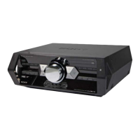
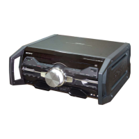
Exploded view showing the side panels, top panel, and CD mechanism.

Exploded Views of Unit Components (Continued)

Back Panel Section Exploded View

Exploded view showing the back panel and its components.

Exploded Views of Unit Components (Continued)

Front Panel Section Exploded View

Exploded view showing the front panel components like display and buttons.

Exploded Views of Unit Components (Continued)

Chassis Section Exploded View

Exploded view of the main chassis and associated parts.

Exploded Views of Unit Components (Continued)

CD Mechanism Section Exploded View

Exploded view of the CD mechanism, including loading and optical parts.

Electrical Parts List - Buttons and Switches

Button Board Components List

List of components for the button boards, including diodes and switches.

Electrical Parts List - Display and Microphone

Display, Mic, and Related Components List

Parts list for display, microphone, and related ICs, diodes, and capacitors.

Electrical Parts List - Microphone and Motherboard

Microphone and Motherboard Components List

Parts list for microphone board capacitors/transistors and motherboard resistors.

Electrical Parts List - Motherboard Capacitors

Motherboard Capacitor List (Part 1)

Comprehensive list of motherboard capacitors with specifications.

Electrical Parts List - Motherboard Capacitors (Continued)

Motherboard Capacitor List (Part 2)

Continuation of the motherboard capacitor list with specifications.

Electrical Parts List - Motherboard Capacitors (Continued)

Motherboard Capacitor List (Part 3)

Final part of the motherboard capacitor list with specifications.

Electrical Parts List - Motherboard Resistors

Motherboard Resistor List (Part 1)

Comprehensive list of motherboard resistors with specifications.

Electrical Parts List - Miscellaneous Components

Miscellaneous Boards and ICs List

Parts list for MS-476, RGB, USB boards, thermistors, and ICs.

Electrical Parts List - Motherboard ICs and Transistors

Motherboard ICs and Transistors List (Part 1)

List of ICs and transistors on the motherboard, including power amplifier drivers.

Electrical Parts List - Motherboard Transistors and Resistors

Motherboard Transistors and Resistors List (Part 1)

List of motherboard transistors and resistors with specifications.

Electrical Parts List - Motherboard Resistors (Continued)

Motherboard Resistor List (Part 2)

Continuation of the motherboard resistor list with specifications.

Electrical Parts List - Motherboard Resistors (Continued)

Motherboard Resistor List (Part 3)

Continuation of the motherboard resistor list with specifications.

Electrical Parts List - Motherboard Resistors (Continued)

Motherboard Resistor List (Part 4)

Continuation of the motherboard resistor list with specifications.

Electrical Parts List - Motherboard Resistors (Continued)

Motherboard Resistor List (Part 5)

Continuation of the motherboard resistor list with specifications.

Electrical Parts List - Motherboard Resistors (Continued)

Motherboard Resistor List (Part 6)

Continuation of the motherboard resistor list with specifications.

Electrical Parts List - Miscellaneous Boards

MS-476, RGB, USB Boards List

Parts list for MS-476, RGB Bar, and USB boards.

Electrical Parts List - USB and Volume Board

USB and Volume Board Components List

Parts list for USB and Volume board ICs, diodes, connectors, and capacitors.

Electrical Parts List - Volume Board (Continued)

Volume Board Transistors and Resistors List

Parts list for volume board transistors and resistors.

Electrical Parts List - Volume Board (Continued)

Volume Board Miscellaneous Parts List

Parts list for miscellaneous volume board components like fans and encoders.

Related product manuals