EasyManua.ls Logo

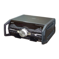
Sony HCD-SPZ90DAB User Manual

Sony HCD-SPZ90DAB
69 pages
To Next Page IconTo Next Page
Page #1 background imageLoading...
Page #1 background image
SERVICE MANUAL
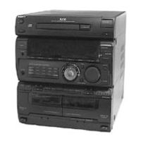
COMPACT DISC DECK RECEIVER
HCD-SPZ90DAB
Ver. 1.0 2006.06
SPECIFICATIONS
CD Section Model Name Using Similar Mechanism HCD-SPZ50
CD Mechanism Name DLM3A
Base Unit Name BU-K6BD83S-WOD
Optical Pick-Up Block Name KSM-213DCP
TAPE Section Model Name Using Similar Mechanism HCD-SPZ50
Tape Transport Mechanism Name CFP42601
– Continued on next page –
9-887-267-01
2006F05-1
Sony Corporation
Personal Audio Division
UK Model
HCD-SPZ90DAB is the amplifier, CD player, tape
deck and tuner section in CMT-SPZ90DB.
Amplifier section
DIN power output (rated): 40 + 40 W (6 ohms at 1 kHz, DIN)
Continuous RMS power output (reference): 50 + 50 W (6 ohms at 1 kHz,
10% THD)
Music power output (reference): 50 + 50 W (6 ohms at 1 kHz, 10% THD)
Inputs
AUDIO IN: Sensitivity 250 mV, impedance 47 kilohms
Outputs
PHONES: Accepts headphones with an impedance of 8 ohms or more
SPEAKER: Accepts impedance of 6 ohms
CD player section
System: Compact disc and digital audio system
Laser Diode Properties
Emission Duration: Continuous
Laser Output*: Less than 44.6μ W
* This output is the value measurement at a distance of 200 mm from
the objective lens surface on the Optical Pick-up Block with 7 mm
aperture.
Frequency response: 20 Hz – 20 kHz (±2 dB)
Wavelength: 780 – 790 nm
Tape deck section
Recording system: 4-track 2-channel, stereo
Frequency response: 50 – 13,000 Hz (±3 dB), using Sony TYPE I
cassettes
Tuner section
FM/DAB stereo tuner
Antenna: FM/DAB lead antenna
FM tuner section:
Tuning range: 87.5 – 108.0 MHz
DAB tuner section:
Frequency range
Band-III: 174.928 (5A) – 239.200 (13F) MHz
* For details, see “DAB frequency table” below.
Question and Answer IconNeed help?

Do you have a question about the Sony HCD-SPZ90DAB and is the answer not in the manual?

Sony HCD-SPZ90DAB Specifications

General IconGeneral
BluetoothYes
USB PlaybackYes
CD PlayerYes
FM TunerYes
NFCYes
TunerDAB/DAB+/FM
FunctionsCD, USB, Bluetooth

Summary

SECTION 1 SERVICING NOTES

NOTES ON HANDLING THE OPTICAL PICK-UP BLOCK OR BASE UNIT

Precautions for handling the optical pick-up block to prevent electrostatic discharge.

NOTES ON LASER DIODE EMISSION CHECK

Safety guidelines for checking laser diode emission.

SECTION 3 DISASSEMBLY

DISASSEMBLY FLOW

Sequential steps for disassembling the unit.

CASE

Procedure for removing the outer case of the unit.

FRONT PANEL ASSY

Instructions for disassembling the front panel assembly.

TAPE MECHANICAL DECK (CFP42601)

Procedure for removing the tape mechanism deck.

MAIN BOARD

Steps for accessing and removing the main circuit board.

BASE UNIT (BU-K6BD83S-WOD ASSY)/ BELT (DLM3A)

Procedure for accessing the base unit and replacing belts.

AMP/SP/POWER BOARDS

Instructions for disassembling amplifier, speaker, and power boards.

DAB MODULE ASSY

Procedure for accessing and removing the DAB module assembly.

SECTION 4 TEST MODE

COLD RESET

Procedure to reset all data to initial conditions.

COMMON TEST MODE

Mode for checking amplifier operations.

PANEL TEST MODE

Mode for testing the fluorescent indicator tube, LEDs, and keys.

CD SHIP MODE

Mode to move the optical pick-up for vibration durability.

CD SHIP MODE & MEMORY CLEAR

Simultaneous CD ship mode and cold reset procedure.

ANTITHEFT LOCK MODE

Mode to prevent sample disc removal from the disc table.

SECTION 5 MECHANICAL ADJUSTMENTS

TORQUE MEASUREMENT

Procedures for measuring torque on the tape deck mechanism.

TAPE TENSION MEASUREMENT

Procedure for measuring tape tension.

SECTION 6 ELECTRICAL ADJUSTMENTS

RECORD/PLAYBACK HEAD AZIMUTH ADJUSTMENT

Procedure for adjusting the record/playback head azimuth.

SECTION 7 DIAGRAMS

Waveforms

IC Block Diagrams

IC Pin Function Description

SECTION 8 EXPLODED VIEWS

OVERALL SECTION

Exploded view of the entire unit with part references.

FRONT PANEL SECTION

Exploded view of the front panel components.

FL SECTION

Exploded view of the FL (fluorescent) display section.

CD SECTION

Exploded view of the CD mechanism and related parts.

POWER SECTION

Exploded view of the power supply unit and related components.

Related product manuals