48
HCD-SPZ90DAB
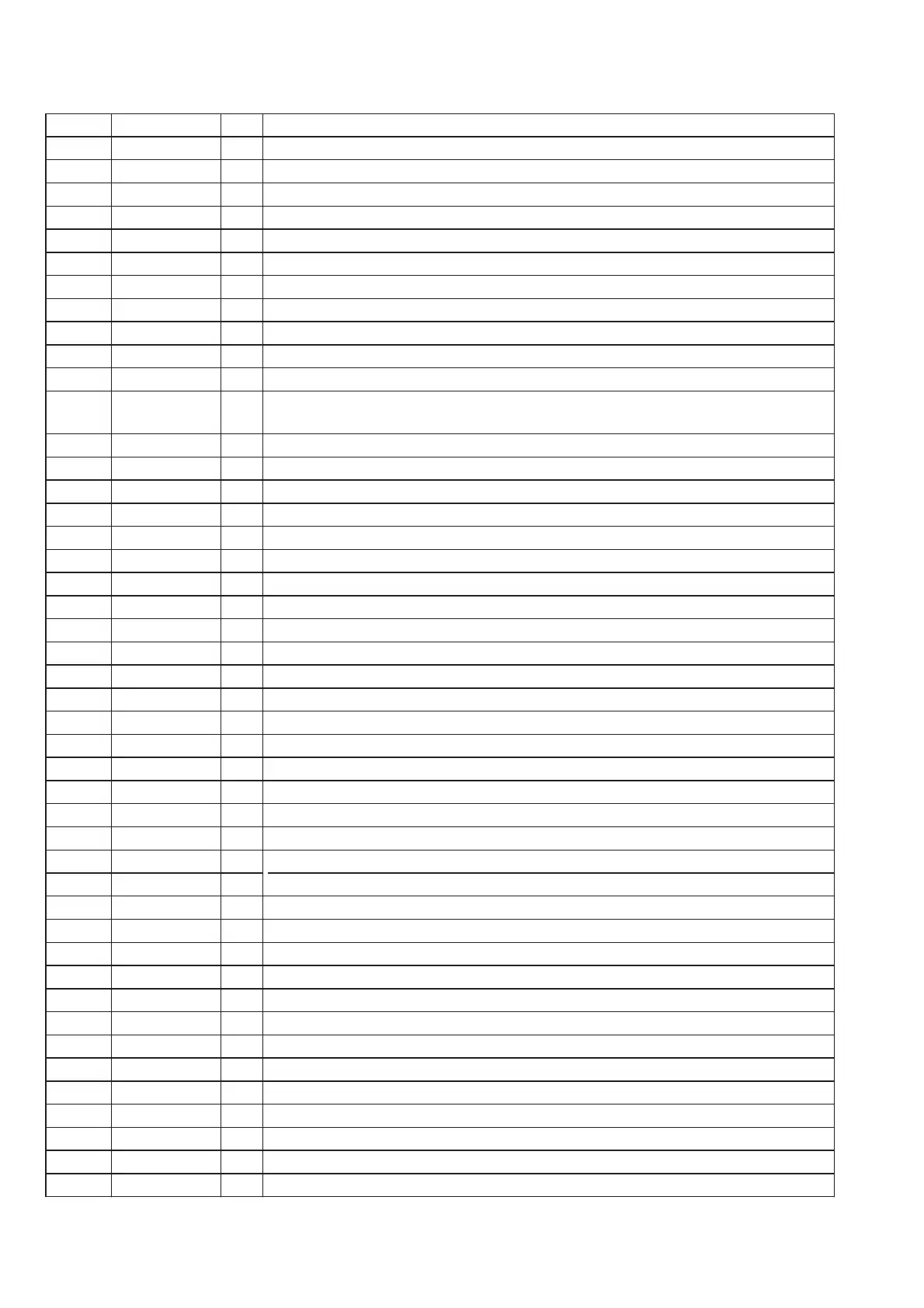
MAIN BOARD IC1301 M30622MGP-A23FPU0 (SYSTEM CONTROLLER)
Pin No.
Pin Name I/O Description
1
FL SD O Serial data output to the fluorescent indicator tube driver
2
FL SCK O Serial data transfer clock signal output to the fluorescent indicator tube driver
3
FL STB O Serial interface strobe signal output to the fluorescent indicator tube driver
4
SIRCS I SIRCS signal input from the remote control receiver
5
MP3 DATA OUT
O MP3 serial data output to the CD DSP
6
MP3 DATA IN I MP3 serial data input terminal
7
MP3 CLK O MP3 serial data transfer clock signal output to the CD DSP
8
BYTE I External data bus width selection signal input terminal
9
CNVSS I Processor mode switch input terminal (for test)
10
XCIN I Sub system clock input terminal (32.768 kHz)
11
XCOUT O Sub system clock output terminal (32.768 kHz)
12
RESET I
System reset signal input from the reset signal generator "L": reset
For several hundreds msec. after the power supply rises, "L" is input, then it changes to "H"
13
XOUT O Main system clock output terminal (5 MHz)
14
VSS - Ground terminal
15
XIN I Main system clock input terminal (5 MHz)
16
VCC - Power supply terminal (+3.3V)
17
NMI I Non-maskable interrupt signal input terminal Not used
18
NO USE O Not used
19
CD SCOR I Subcode sync (S0+S1) detection signal input from the CD DSP
20
AC CUT I AC cut on/off detection signal input terminal "L": AC cut on
21
NO USE O Not used
22
NO USE O Not used
23
SW8 I Disc table open detection switch input terminal
24
SW7 I Disc chucking detection switch input terminal
25
SW6 I Disc table close detection switch input terminal
26
SW5 I Disc stocking detection switch input terminal
27
NO USE O Not used
28
SW3 I Cam position detection switch input terminal
29
IIC CLK I IIC data reading clock signal input terminal Not used
30
IIC DATA I IIC data input terminal Not used
31
DAB TXD
O
Serial data output to the DAB tuner module
32
DAB RXD
I
Serial data input from the DAB tuner module
33
SW2 I Cam position detection switch input terminal
34
SW1 I Cam position detection switch input terminal
35
CD DATA O CD serial data output to the CD DSP
36
CD SENS I Internal status (SENSE) signal input from the CD DSP
37
CD CLK O CD serial data transfer clock signal output to the CD DSP
38
CDM SD I CD mechanism power protect on/off detection signal input terminal "H": protect on
39
M2+ O Cam gear motor control signal output terminal (forward direction)
40
M2- O Cam gear motor control signal output terminal (reverse direction)
41
M1+ O Loading motor control signal output terminal (forward direction)
42
M1- O Loading motor control signal output terminal (reverse direction)
43
CD XLT O CD serial data latch pulse signal output to the CD DSP
44
MP3 ACK I MP3 acknowledge signal input from the CD DSP
45
MP3 REQ O MP3 data request signal output to the CD DSP




 To Next Page