AUDIO POWER SPECIFICATIONS
POWER OUTPUT AND TOTAL HARMONIC
DISTORTION:
(US model only)
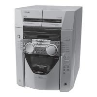
SHAKE-33
With 4 ohm loads, both channels driven, from
40 – 600 Hz; rated 180 watts per channel
minimum RMS power, with no more than
0.7% total harmonic distortion from 250
milliwatts to rated output.
Amplifi er section
The following are measured at
US model:
AC 120 V, 60 Hz
MX model:
AC 120 V – 240 V, 60 Hz
AEP, UK model:
AC 220 V – 240 V, 50/60 Hz
E51 model:
AC 220 V – 240 V, 50 Hz
Other models:
AC 120 V – 240 V, 50/60 Hz
SHAKE-77
WF (Woofers)/MID (Mid speakers)/
TW (Tweeters)
Power Output (rated):
350 W + 350 W (at 4 ohms, 1 kHz,
1% THD)
RMS output power (reference):
600 W + 600 W (per channel at
4 ohms, 1 kHz)
SW (Subwoofers)
RMS output power (reference):
1,200 W + 1,200 W (per channel at
8 ohms, 100 Hz)
SHAKE-33
WOOFERS
Power Output (rated):
350 W + 350 W (at 4 ohms, 100 Hz,
1% THD)
RMS output power (reference):
600 W + 600 W (per channel at
4 ohms, 100 Hz)
MID (Mid speakers)/TWEETERS
RMS output power (reference):
500 W + 500 W (per channel at
5 ohms, 1 kHz)
Inputs
AUDIO IN 1/PARTY CHAIN IN L/R
Voltage 2 V, impedance 47 kilohms
AUDIO IN 2 L/R
Voltage 2 V, impedance 47 kilohms
MIC (SHAKE-77 only)
Sensitivity 1 mV, impedance 10 kilohms
(USB) A, (USB) B port
Type A
Outputs
AUDIO OUT/PARTY CHAIN OUT L/R
Voltage 2 V, impedance 1 kilohm
USB section
Supported bit rate
WMA:
48 kbps – 192 kbps, VBR, CBR
AAC:
48 kbps – 320 kbps, VBR, CBR
Sampling frequencies
WMA: 44.1 kHz
AAC: 44.1 kHz
Supported USB device
Mass Storage Class
Maximum current
500 mA
Disc/USB section
Supported bit rate
MPEG1 Layer-3:
32 kbps – 320 kbps, VBR
MPEG2 Layer-3:
8 kbps – 160 kbps, VBR
MPEG1 Layer-2:
32 kbps – 384 kbps, VBR
Sampling frequencies
MPEG1 Layer-3:
32 kHz/44.1 kHz/48 kHz
MPEG2 Layer-3:
16 kHz/22.05 kHz/24 kHz
MPEG1 Layer-2:
32 kHz/44.1 kHz/48 kHz
Disc player section
System
Compact disc and digital audio system
Laser Diode Properties
Emission Duration: Continuous
Laser Output*: Less than 44.6 µW
* This output is the value
measurement at a distance of
200 mm from the objective lens
surface on the Optical Pick-up
Block with 7 mm aperture.
Frequency response
20 Hz – 20 kHz
Signal-to-noise ratio
More than 90 dB
Dynamic range
More than 88 dB
Tuner section
FM stereo, FM/AM superheterodyne tuner
Antenna:
FM lead antenna
AM loop antenna
FM tuner section
Tuning range
US
model:
87.5 MHz – 108.0 MHz (100 kHz step)
Other models:
87.5 MHz – 108.0 MHz (50 kHz step)
AM tuner section
Tuning range
AEP, UK model:
531 kHz – 1,602 kHz (9 kHz step)
AUS, E2, E51, US, MX models:
531 kHz – 1,710 kHz (9 kHz step)
530 kHz – 1,710 kHz (10 kHz step)
Other models:
531 kHz – 1,602 kHz (9 kHz step)
530 kHz – 1,610 kHz (10 kHz step)
Bluetooth section
Communication system
Bluetooth Standard version 3.1
Output
Bluetooth Standard Power Class 2
Maximum communication range
Line of sight approx. 10m
1)
Frequency band
2.4 GHz band (2.4000 GHz –
2.4835 GHz)
Modulation method
FHSS (Freq Hopping Spread
Spectrum)
Compatible Bluetooth profiles
2)
A2DP (Advanced Audio Distribution
Profile)
AVRCP 1.3 (Audio Video Remote
Control Profile)
SPP (Serial Port Profile)
Supported codecs
SBC (Sub Band Codec)
AAC (Advanced Audio Coding)
1)
The actual range will vary depending on
factors such as obstacles between devices,
magnetic fields around a microwave oven,
static electricity, reception sensitivity,
antenna’s performance, operating system,
software application, etc.
2)
Bluetooth standard profiles indicate the
purpose of Bluetooth communication
between devices.



 Loading...