– 2 –
Section Title Page
TABLE OF CONTENTS
Specifications ...................................................................................1
1. GENERAL ...............................................................................3
2. DISASSEMBLY
2-1. Front Panel Section Removal ............................................ 4
2-2. CD Block Removal............................................................4
2-3. Cassette LID (A)/(B) Assy,
Mechanism Deck Removal................................................5
3. ADJUSTMENTS
3-1. Mechanical Adjustments ...................................................6
3-2. Electrical Adjustments.......................................................6
4. EXPLANATION OF IC TERMINALS ................................11
5. DIAGRAMS
5-1. Block Diagram ................................................................ 13
5-2. Circuit Boards Location ..................................................15
5-3. Printed Wiring Boards –Main Section–...........................16
5-4. Schematic Diagram–Main Section– ................................ 19
5-5. Schematic Diagram –TC Section– ..................................23
5-6. Printed Wiring Boards–TC Section– ............................... 27
5-7. Schematic Diagram–CD Section– ................................... 29
5-8. Printed Wiring Boards –CD Section– .............................31
5-9. IC Block Diagrams .......................................................... 35
Section Title Page
6. EXPLODED VIEWS
6-1. Chassis Section................................................................ 38
6-2. Front Panel Section ......................................................... 39
6-3. TC Mechanism Section-1 (TCM-220WR2).................... 40
6-4. TC Mechanism Section-2 (TCM-220WR2).................... 41
6-5. CD Mechanism Section (CDM38-5BD19) .....................42
6-6. Chassis Section (CDM38-5BD19) ..................................43
6-7. Base Unit Section (BU-5BD19) ......................................44
7. ELECTRICAL PARTS LIST ...............................................45
SERVICING NOTE
r
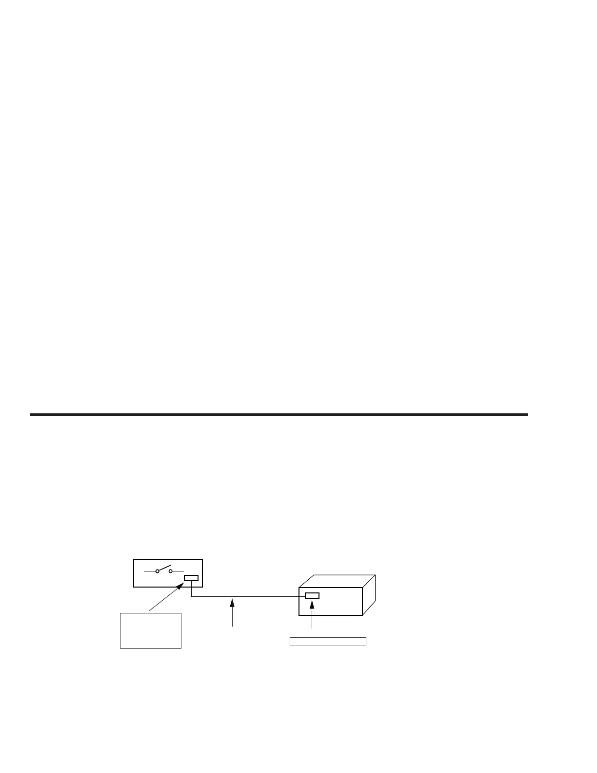
Supplying power during servicing
This equipment cannot operate without using a separate power supply. Connect to the STR-W55/W77AV when performing service work.
To apply power set the SYSTEM POWER switch on the Tuner/Amp to ON.
When other units are not available use the PFJ-1 power supply jig.
When using the PFJ-1, simultaneously press the CD STOP button and the DECK A ) (fast rightward) button to turn on the power.
PFJ-1
(Power Supply Jig)
POWER SW
Set
connector cable 17P
(Supplied with set)
CN151 17P
SYSTEM CONTROL 1
FH-E939,838,737,
MHC-6600, 5600,
3600, 2600
CDP/TC
[Connection Diagram]