8
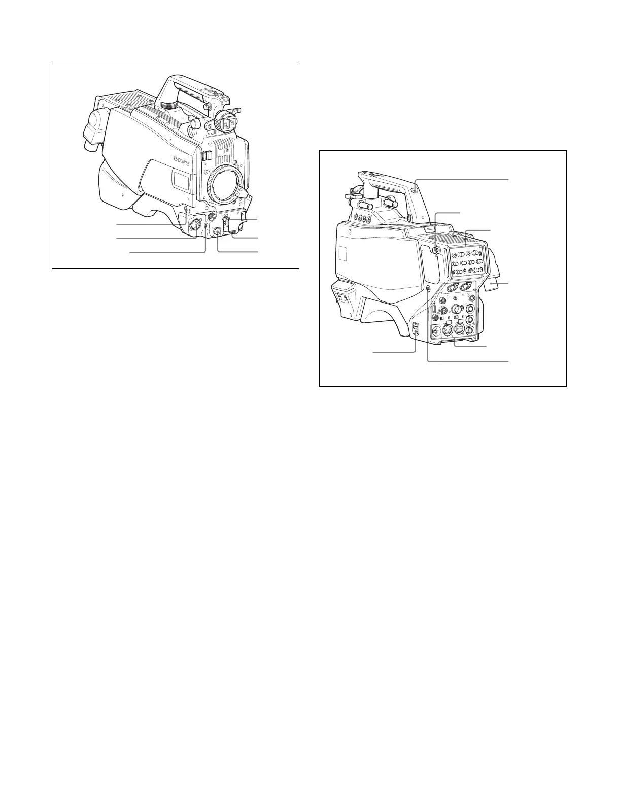
Front left
a RET 1 (return video 1) button
The return video 1 signal from the camera control unit is
monitored on the viewfinder screen while this button is
pressed. It function the same as the RET 1 buttons on the
handle (page 7) and that on the operation panel on the rear of
the camera (page 9 or 10).
You can also assign other functions to this button, using the
menu displayed on the viewfinder screen.
b MIC 1 IN (microphone 1 input) connector (XLR 3-pin)
Connect a microphone.
This connector and the AUDIO IN CH-1 connector (page 11)
on the operation panel on the rear of the camera are
alternately activated with the CH1 audio input select switch
(page 11).
c MIC (microphone) power switch
+48V: To supply a power of +48 V to the connected
microphone.
OFF: Not to supply a power to the connected microphone.
d SHUTTER switch
For setting the electronic shutter functions when the camera is
used in standalone status without connecting a camera control
unit.
OFF: The electronic shutter does not function.
ON: The electronic shutter is activated.
SEL: The shutter speed and shutter mode change each time
the switch is set to this position.
For details, see “Setting the Electronic Shutter” on page 19.
e INTERCOM LEVEL control
To adjust the intercom/earphone volume level.
The intercom level adjustment is enabled when the
INTERCOM 1 and 2 LEVEL/MIC switches (on the SY-type
operation panel, page 9) or the LEVEL switch (on the
European-type operation panel, page 10) on the rear of the
camera are set to “FRONT.”
f RET 2 (return video 2) button
When this button is pressed, the picture on the viewfinder
screen changes to the return video signal selected with the
RET 2 select switch (page 9 or 10) on the operation panel on
the rear of the camera.
You can also assign other functions to this button, using the
menu displayed on the viewfinder screen.
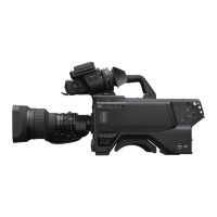
Rear
a CAMERA POWER switch
CCU: Power is supplied from the camera control unit.
EXT: Power is supplied through the DC IN connector.
b Tally lamp and switch
ON: The tally lamp lights when a tally signal is input to the
connected camera control unit or a call signal is
generated in response to pressing of a CALL button.
OFF: The tally lamp is prevented from lighting.
c CCU (Camera Control Unit) connector (optical/
electrical multi-connector)
Connect a camera control unit using an optical electro-
composite cable.
d CALL button
When this button is pressed, the red tally lamp of the RCP-
1000-series Remote Control Panel or the MSU-1000-series
Master Setup Unit will light. Use to call the operator of the RCP
or MSU.
H
D
M
U
LTI FO
RM
A
T
S
ER
IE
S
1
2
3
4
5
6
1
2
3
4
Operation panel
(page 9)
Shoulder strap fitting
post (page 6)
Connector panel
(page 10)