HS-MB1
5
1
IN
2
10V19.5V
ZONE 1
19.5V
ZONE 2
19.5V
ZONE 3
19.5V
ZONE 4
DC IN
CAMERA
19.5V
ZONE 5
19.5V
ZONE 6 ZONE 7
19.5V 19.5V
ZONE 8
DC IN
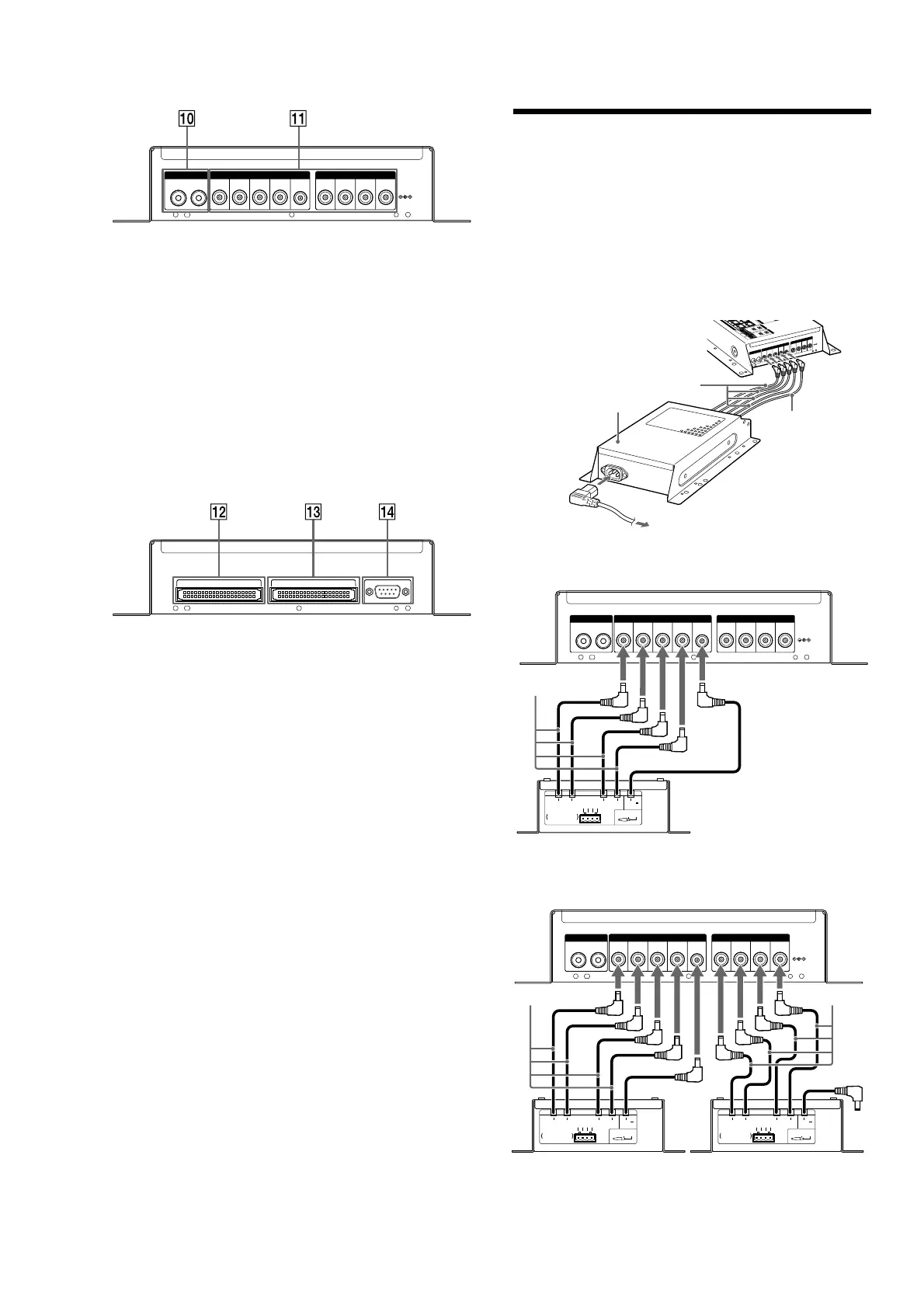
+ CAMERA 1/2 IN jack
Pin jack for video input from a video camera.
, DC IN
Connect the DC IN terminals using the Power Supply (HS-AC1)
(supplied).
ZONE 1 – 4: Connect all four of the 19.5 V plugs and the 10 V plug
of the Power Supply (HS-AC1) (supplied). e ZONE 1
19.5 V cable also supplies power to the HS-MB1 main
unit.
ZONE 5 – 8: If you use the ZONE 5 ~ 8 terminals in addition to the
ZONE 1 ~ 4 terminals, connect all four of the 19.5 V
plugs of a second Power Supply (HS-AC1) (optional).
e 10 V plug of this second Power Supply (HS-AC1)
(optional) is not used.
ZONE EXPANSION OUT ZONE EXPANSION IN
RS-232C
- ZONE EXPANSION OUT
IDE (Integrated Drive Electronics) terminal for sending a source to
another Distribution Panel (HS-MB1). Use an IDE cable (not
supplied) for the connection.
. ZONE EXPANSION IN
IDE (Integrated Drive Electronics) terminal to input a source from
another Distribution Panel (HS-MB1). Use an IDE cable (not
supplied) for the connection.
Note
Only if another Distribution Panel (HS-MB1) is connected for expansion is
its ZONE EXPANSION IN terminal used.
/ RS-232C
Connect to a computer for rmware updates or addition of another
Distribution Panel (HS-MB1) (Stack connection). Use an RS-232C
cross cable (not supplied) for connection.
Note
With another Distribution Panel (HS-MB1), you can connect 16 units
maximum in one system network. All units can receive audio sources. Each
unit in zone 1, 2, 3, and 4 can accept video sources. However, if you use two
Distribution Panels (HS-MB1) in one system network, available input sources
are up to four.
Connecting the AC power cord
Before connecting the AC power cord to a wall outlet, connect all parts
of the system to the unit. e indicator lights green when the AC power
cord is connected to the wall outlet and the HS-MB1 is engaged.
Notes
●
Aer completing all the connections, make sure there are no misconnections or
improper wiring before plugging the Power Supply (HS-AC1) (supplied) into
the wall outlet. Improper wiring or misconnections may cause damage to the
unit.
●
Use the Power Supply (HS-AC1) (supplied) for this model, as other AC adapters
may cause a malfunction.
1
I
N
2
1
0
V1
9
.5V
ZON
E
1
1
9
.
5
V
ZO
NE
2
1
9
.5V
Z
O
NE3
1
9
.
5V
Z
ON
E
4
DC
IN
C
AM
ERA
19
.5
V
ZONE 5
1
9
.
5
V
ZONE 6 Z
ONE
7
1
9.
5
V 19
.
5
V
ZONE8
DC
IN
Power Supply (HS-AC1)
(supplied)
19.5 V cable
10 V cable
To the wall outlet
When using the ZONE 1 ~ 4 terminals (4 Keypads (HS-KP1) max.)
1
IN
2
10V19.5V
ZONE 1
19.5V
ZONE 2
19.5V
ZONE 3
19.5V
ZONE 4
DC IN
CAMERA
19.5V
ZONE 5
19.5V
ZONE 6 ZONE 7
19.5V 19.5V
ZONE 8
DC IN
19.5V
2.5A
(
LPS
)
19.5V
2.5A
(
LPS
)
19.5V
2.5A
(
LPS
)
19.5V
2.5A
(
LPS
)
DC CABLES x4
CONNECTORTERMINALS x2
DC10V
0.25A
(
LPS
)
DC OUT
GND
19.5V
2.5A
(
LPS
)
GN
D
1
9
.
5
V
2.5A
(
L
P
S
)
DC 19.5V
=
TOTAL4.5 A
HS-MB1
19.5 V cable
10 V cable
Power Supply (HS-AC1) (supplied)
When using the ZONE 1 ~ 8 terminals (8 Keypads (HS-KP1) max.)
1
IN
2
10V19.5V
ZONE 1
19.5V
ZONE 2
19.5V
ZONE 3
19.5V
ZONE 4
DC IN
CAMERA
19.5V
ZONE 5
19.5V
ZONE 6 ZONE 7
19.5V 19.5V
ZONE 8
DC IN
19.5V
2.5A
(
LPS
)
19.5V
2.5A
(
LPS
)
19.5V
2.5A
(
LPS
)
19.5V
2.5A
(
LPS
)
DC CABLES x4
CONNECTORTERMINALS x2
DC10V
0.25A
(
LPS
)
DC OUT
GND
1
9
.
5
V
2.5
A
(
L
P
S
)
GND
19.5
V
2
.
5A
(
LPS
)
DC 19.5V
=
TOTAL4.5 A
19.5V
2.5A
(
LPS
)
19.5V
2.5A
(
LPS
)
19.5V
2.5A
(
LPS
)
19.5V
2.5A
(
LPS
)
DC CABLES x4
CONNECTORTERMINALS x2
DC10V
0.25A
(
LPS
)
DC OUT
G
N
D
1
9
.
5
V
2
.
5
A
(
LPS
)
G
N
D
19.
5
V
2
.
5A
(
LPS
)
DC 19.5V
=
TOTAL4.5 A
HS-MB1
19.5 V cable
10 V cable
Power Supply (HS-AC1) (supplied)
Power Supply (HS-AC1) (optional)
19.5 V cable
10 V cable
Note
e 10 V cable of the second Power Supply (HS-AC1) (not supplied) is not used if
you use the ZONE 5 ~ 8 terminals.