HS-MB1
4
SECTION 2
GENERAL
This section is extracted
from instruction manual.
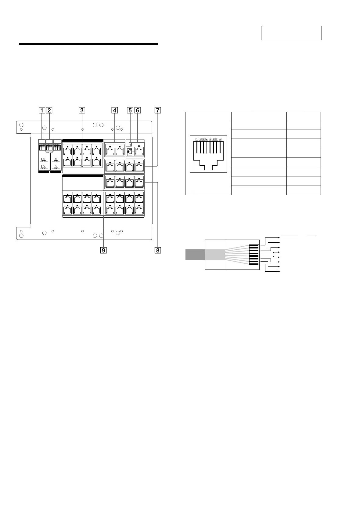
Hooking up the HS-MB1
Before hooking up the HS-MB1, be sure the AC power cord is
unplugged.
Note
If a CAT5 cable is connected to the wrong RJ45 terminal, units or devices
connected to HS-MB1 may be damaged when you plug in the AC power cord.
Te rm in als ", $, ', and ( supply DC voltage, so make sure of all connections
before plugging in the AC power cord.
ZONE 1
A
B
ZONE 2
A
B
ZONE 3
A
B
ZONE 4
A
B
ZONE 5
A
B
ZONE 6
A
B
ZONE 7
A
B
ZONE 8
A
B
TO KEYPAD HS-KP1
TO AV WAL L P ORT HS-W V1
TO COMPONENT VIDEO BALUN CAV-CVB1
TO DIGITAL MEDIA WALL PORT
HS-WD1
OUTPUT
DOOR 2
INPUT
ZONE 1
F
ZONE 2
F
ZONE 3
F
ZONE 4
F
SOURCE 1
E
SOURCE 2
E
SOURCE 3
E
SOURCE 4
E
SOURCE 1
C
D
SOURCE 2
C
D
SOURCE 3
C
D
SOURCE 4
C
D
G
SOURCE DMPORT
H
B
SERVICE
ZONE
LOCAL
MODE
DB2
OFF 2 3
2E1
DB1
2E1
CHIME
2E1
GAIN
123
DOOR 1
MODE
OFF 2 3
GAIN
123
DB1/DB2
Connect the conductor cable for Doorbell.
MODE: Set 2 or 3 depending on the Doorbell manufacturer.
GAIN: Set the mic/speaker level of the Doorbell.
CHIME
Connect the external chime.
INPUT
SOURCE 1 ~ 4
$%
RJ45 terminals to input audio signal from AV Wall Port(s)
(HS-WV1).
Use both terminals for the connection.
Note
When you connect a Multi Channel AV Receiver to the HS-MB1, be sure to
use the SOURCE 1 terminals. e Multi Channel AV Receiver will not work
with the SOURCE 2, 3, or 4 terminals.
SOURCE DMPORT ()
RJ45 terminals to input Digital Media Port signal from Digital Media
Wall Port(s) (HS-WD1).
Use both terminals for the connection.
Note
If a DIGITAL MEDIA PORT adapter is connected to a Multi Channel AV
Receiver which is connected to the HS-MB1, you cannot use the SOURCE
DMPORT terminals of the HS-MB1.
DC IN indicator
SERVICE
#
RJ45 terminals for Keypad (HS-KP1) rmware updates.
ZONE: Select this when updating the Keypad (HS-KP1) rmware.
LOCAL: Select this when updating this unit’s rmware.
SOURCE 1 ~ 4
&
RJ45 terminals to input video signal from AV Wall Port(s)
(HS-WV1).
OUTPUT
ZONE 1 ~ 4 '
RJ45 terminals send a video signal source to the component video.
Use a Component Video Balun (CAV-CVB1) for the connection.
CAT5 RJ45 Pinout
When you connect the Component Video Balun (CAV-CVB1), the
CAT5 RJ45 pinouts use the T568B standard. Refer to the illustration
below.
Pinout Wire color
Pin 1
BLUE/Pb (R) White/Orange
Pin 2
BLUE/Pb (T) Orange
Pin 3
GREEN/Y (R) White/Green
Pin 4
GND Blue
Pin 5
+11V White/Blue
Pin 6
GREEN/Y (T) Green
Pin 7
RED/Pr (R) White/Brown
Pin 8
RED/Pr (T) Brown
CAT5 cable
Be sure to use Category 5e straight-through cables, and the wiring
connection is correct. See the illustration below for details on
connections.
White/Orange
Wire color
Orange
White/Green
Blue
White/Blue
Green
White/Brown
Brown
1
Pin No.
2
3
4
5
6
7
8
ZONE 1 ~ 8 "#
RJ45 terminals for Keypad (HS-KP1).
Use both terminals for the connection.
Note
If you use the ZONE 5 ~ 8 terminals, you need to connect the additional
Power Supply (HS-AC1) (optional) to ZONE 5 – 8 DC IN.
Note on installing CAT5 cables
e following lengths of cable(s) can extend up to 200 feet:
●
e combined length of the two longest cables connecting the HS-MB1 to an
AV Wall Port (HS-WV1) and a Keypad (HS-KP1).
●
e combined length of the cable connecting the HS-MB1 to the Digital Media
Wall Port (HS-WD1) and the longest cable connecting to a Keypad (HS-KP1).
●
e length of the longest cable connecting the HS-MB1 to a Component Video
Balun (CAV-CVB1).