HS-MB1
7
Updating the rmware
You can update the rmware from a computer by connecting the RS-
232C cross cable (not supplied).
To the computer
Z
O
N
E
E
XPAN
SION IN
ZONE
EXPA
NSION OUT
R
S
-
2
32C
RS-232C cross cable
(not supplied)
When updating the Distribution Panel (HS-MB1)
SERVICE
ZONE
LOCAL
B
Switch to “LOCAL”
When updating rmware the Keypad (HS-KP1) (not supplied)
individually
Follow the procedure below to update the Keypad (HS-KP1) you want to
update:
Note
Be sure to unplug the AC power cord when disconnecting and connecting a CAT5
cable.
Disconnect the CAT5 cable from the ZONE # terminal.
Set the SERVICE switch to “ZONE.”
Connect the CAT5 cable to the SERVICE # terminal.
When the update is nished, disconnect the CAT5 cable from the
SERVICE # terminal.
Reconnect the CAT5 cable to the ZONE # terminal.
Aer updating all keypads, set the SERVICE switch to “LOCAL.”
SERVICE
ZONE
LOCAL
B
VOLUME
MUTING
MENU
MIC
RETURN/EXIT OPTIONS
Keypad (HS-KP1)
(not supplied)
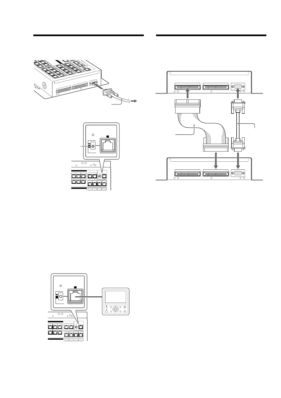
Expanding the Distribution Panel
(HS-MB1) (Stack connection)
You can connect up to a maximum of 16 Keypads (HS-KP1) (not
supplied) by adding another HS-MB1.
ZONE EXPANSION OUT ZONE EXPANSION IN
RS-232C
ZONE EXPANSION OUT ZONE EXPANSION IN
RS-232C
HS-MB1 (main unit)
IDE cable
(not supplied)
HS-MB1 (sub unit)
RS-232C cross cable
(not supplied)
Notes
●
When connecting the additional Distribution Panel (HS-MB1) (sub unit), the
SOURCE 1 ~ 4 & terminals of the sub unit cannot be used.
●
When connecting the additional Distribution Panel (HS-MB1) (sub unit), video
signal input from SOURCE 1 ~ 4 & terminals of the main unit cannot output
from the ZONE 1 ~ 4 ' terminals of the sub unit.
●
When updating the rmware, disconnect the RS-232C cross cable (not
supplied) that connects the additional Distribution Panel (HS-MB1) (sub unit),
and connect the computer.
●
When you connect the units, use an IDE cable with pin 20 opening.
●
Connect all Power Supplies (HS-AC1) to the wall outlets at the same time.
●
Set the SERVICE switch to “LOCAL.”