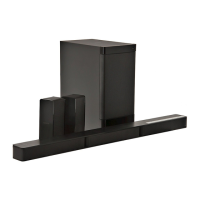
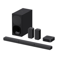
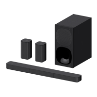
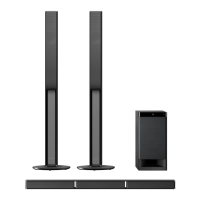
HT-RT4/RT40
14
2-8.
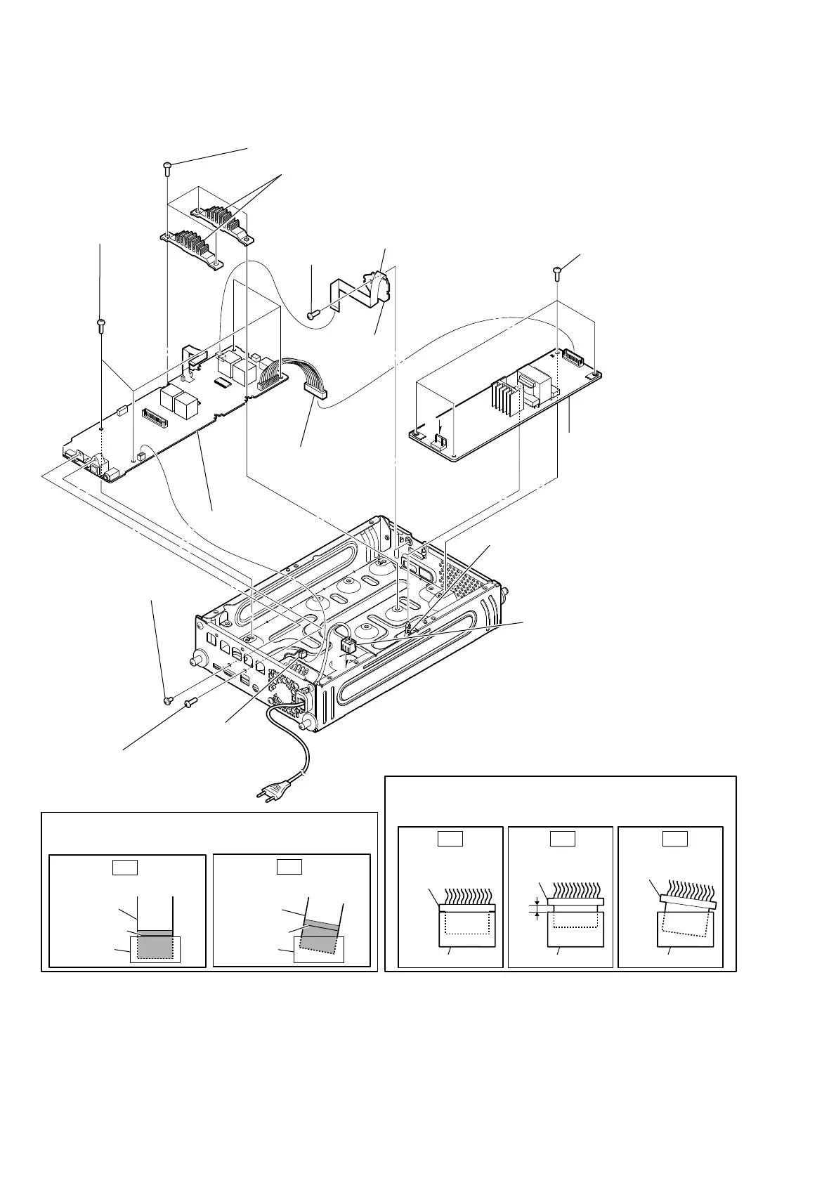
MAIN BOARD (RT4), EG4 MAIN BOARD (RT40), CONNECTOR BOARD, SWITCHING REGULATOR
• Abbreviation
E12 : 220-240 V AC area in E model
A
A
1 wire (flat type)
(20 core) (CN2006)
0 one screw
(+BV3 (3-CR))
4 one screw (+BV3 (3-CR))
qa CONNECTOR
board
2 CN101 (9P)
5 one screw (+B 3 X 5)
8 four screws
(+BVTP 3 X 8
TYPE2 IT-3)
qd four screws
( +BVTP 3 X 8 TYPE2 IT-3)
qf Remove REGULATOR,
SWITCHING 3L405W-4 (EXCEPT E12) /
REGULATOR, SWITCHING 3L405W-5 (E12)
from holder, PC board.
3 CN3200 (2P)
qs CN1 (2P)
qg REGULATOR,
SWITCHING 3L405W-4
(EXCEPT E12) /
REGULATOR,
SWITCHING 3L405W-5 (E12)
6 four screws (+BVTP 3 X 8 TYPE2 IT-3)
9
MAIN board (RT4) /
EG4 MAIN board (RT40)
7 heat sink (EL-SW)
Note: When installing the heat sink (EL-SW), spread the compound referring to
"NOTE OF REPLACING THE IC1000 AND IC1002 ON THE MAIN BOARD (RT4)
OR EG4 MAIN BOARD (RT40) AND THE COMPLETE MAIN BOARD (RT4)
OR COMPLETE EG4 MAIN BOARD (RT40)" on page 5.
– Rear view –
Note 1:
When installing the wire (flat type), ensure that the
colored line is not slanted after insertion.
colored line
colored line
Insert is straight to the interior. Insert is incline
wire (flat type)
connectorconnector
OK
NG
wire (flat type)
Note 2:
When you install the connector, please install them correctly.
There is a possibility that this machine damages when not
correctly installing it.
Insert is shallow
Insert is straight
to the interior.
connector
Insert is incline
connector
connector
connector
connector connector
OK NG NG
 Loading...