EasyManua.ls Logo

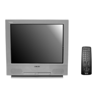
Sony KV-21FE13 User Manual

Sony KV-21FE13
108 pages
To Next Page IconTo Next Page
Page #1 background imageLoading...
Page #1 background image
TRINITRON
®
COLOR TELEVISION
SERVICE MANUAL
BA-5
CHASSIS
MODEL NAME REMOTE COMMANDER DESTINATION CHASSIS NO.
Self Diagnosis
Supported model
KV-21FE13
9-965-910-01
KV-21FE13
RM-Y173 E SCC-S56EA
KV-21FE13C
RM-Y173 E SCC-S56FA
KV-21FM13
RM-Y172 E SCC-S56GA
KV-21FM13C
RM-Y172 E SCC-S56HA
RM-Y173

Table of Contents

Question and Answer IconNeed help?

Do you have a question about the Sony KV-21FE13 and is the answer not in the manual?

Sony KV-21FE13 Specifications

General IconGeneral
BrandSony
ModelKV-21FE13
CategoryTV
LanguageEnglish

Summary

SPECIFICATIONS

WARNINGS AND CAUTIONS

SAFETY-RELATED COMPONENT WARNING!!

Replace critical components with Sony parts; follow manual procedures for safety.

SAFETY CHECK-OUT

Leakage Test

Test AC leakage from exposed metal parts to earth ground, not exceeding 0.5 mA.

SELF-DIAGNOSTIC FUNCTION

Diagnostic Test Indicators

STANDBY/TIMER LED flashes indicate probable cause of error; number of flashes translates to problem source.

SECTION 1: DISASSEMBLY

1-4. PICTURE TUBE REMOVAL

Procedure for removing the picture tube, including safety precautions.

SECTION 2: SET-UP ADJUSTMENTS

2-2. CONVERGENCE

Adjusting red, green, and blue dot convergence for optimal picture quality using magnets and controls.

2-5. METHOD OF SETTING THE SERVICE ADJUSTMENT MODE

Procedure to enter and operate the TV's service adjustment mode using the remote commander.

SECTION 3: SAFETY RELATED ADJUSTMENTS

3-2. B+ VOLTAGE CONFIRMATION AND ADJUSTMENT

Confirming and adjusting the B+ voltage level, a critical safety parameter.

SECTION 4: CIRCUIT ADJUSTMENTS

4-1. SETTING THE SERVICE ADJUSTMENT MODE

Procedure to access the service adjustment mode via the remote commander.

SECTION 5: DIAGRAMS

5-1. CIRCUIT BOARDS LOCATION

Identifying the physical location of the main circuit boards within the TV.

SECTION 6: EXPLODED VIEWS

6-1. CHASSIS (KV-21FE13/21FE13C/21FM13/21FM13C)

Exploded view of the TV chassis, showing major components and their assembly.

SECTION 7: ELECTRICAL PARTS LIST

Related product manuals