53
English
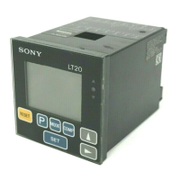
5-1-2. BCD model
(only LT10-105B/205B, LT11-101B/201B)
Proceeds to the next setting mode from “5-1-1. Basic settings” step 4.
1. BCD logic
Setting the BCD output logic.
“+” is true logic.
“–” is false logic.
Exception : Logic for the DRQ, READY, and alarm
terminals cannot be changed.
(See P63 “7. BCD output”)
2. BCD output format
Setting the BCD output format.
:BCD is output
according to the DRQ
signal input, and the
resulting status is
held even if the DRQ
signal goes off.
: BCD is output according
to DRQ signal input,
and assumes high-
impedance status
when there is no DRQ
signal input.
Initial settings are now complete for the BCD model.
Press
MODE
to return to the measuring state.
Note
• With the LT10 series, 0.001 mm and –0.001 mm (0.0001"
and –0.0001") are not avaible.
• When the addition A+B is chosen the direction for B can
be selected, but its resolution will be the same as that of A.
4. Selecting the start input terminal (terminals) function
(See P60 “6. Terminals I/O”.)
:
Start function
When the peak-hold is
chosen setting this
terminal to “L” (ON) sets
the peak-hold value to
the current value and
restarts the storing
procedure.
: Hold function
When using the current value measuring mode
with the start function, setting this terminal to
“L” (ON) stores the output and display of the
Go/No Go comparison at that point in time.
Note
At this time, display and Go/No Go
comparison output storage by the DRQ input
for the BCD model and EXT. IN input for the
RS-232C model is invalidated.
Initial settings are now complete for the standard model.
Pressing
MODE
.. Basic model → Returns to the measuring state.
BCD model → Go to section 5-1-2.
RS-232C model → Go to section 5-1-3.
factory-set
factory-set
factory-set
 Loading...