12
Connecting Devices
Connection
Connecting Devices
This section describes the connection procedure for the
following system configuration as an example.
• MVS-6520 or MVS-3000A Switcher Processor
(with MKS-6550 Format Converter Board and MKS-
6570 Digital Multi Effect Board installed)
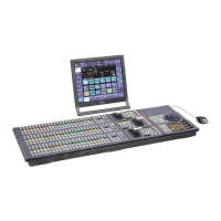
• ICP-6520 Control Panel
• ICP-6511 Menu Panel
• Cameras for recording (4)
• VTRs for playback (2)
• Character generator (1)
• Video monitors (2)
• Monitor for multi viewer (1)
The MVS-3000 does not support the MKS-6570 DME
board.
MVS System Connection
1
Connect the power supply.
Switcher processor
a Connect the U terminal to the system ground.
b Connect the ~AC IN A and B connectors to the 100
V to 240 V AC power supplies using power cords
(not supplied).
Control panel
a Connect the U terminal to the system ground.
b Connect the ~AC IN A and B connectors to the 100
V to 240 V AC power supplies using power cords
(not supplied).
Menu panel
a Connect the supplied AC adaptor to the DC IN
connector, then connect the AC adaptor using a
power cord (not supplied).
Notes
MVS
DEVICE 1
DEVICE
DVI-D
DVI-D
MVS
U
U
MVS-6520/3000A Switcher Processor ICP-6511 Menu Panel
ICP-6520 Control Panel
AC power supplies
AC adaptor
AC power
supplies
LAN cable (straight type)
DVI cable
USB cable

 Loading...


