PHA-1A/1AEU
22
MAIN BOARD IC702 PIC16F1455T-I/ML (CHARGE CONTROLLER)
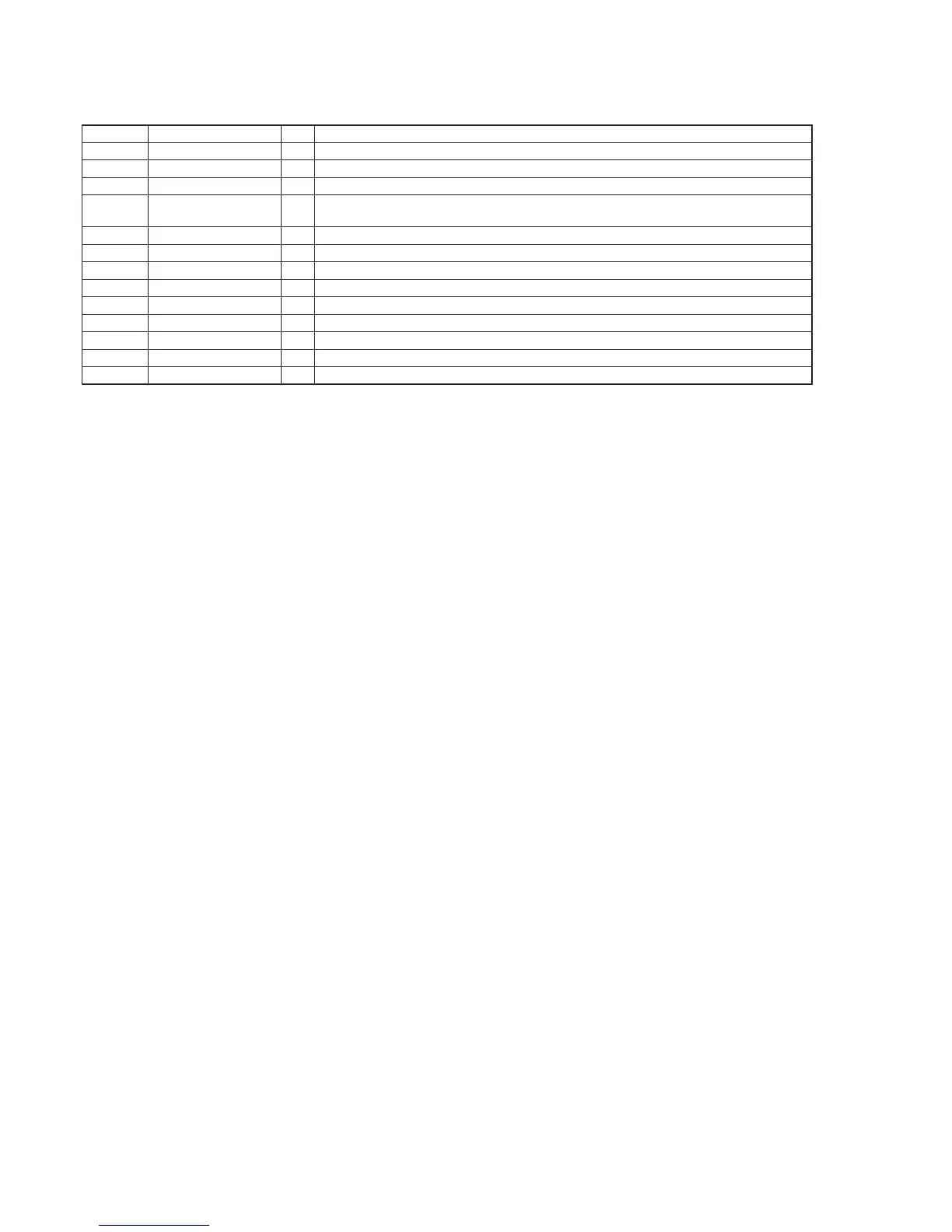
Pin No. Pin Name I/O Description
1 C_LED O LED drive signal output terminal for the POWER/CHG indicator (red color) “H”: LED on
2 TEMP I TH temperature monitoring signal input terminal
3 RST - Not used
4 CHD_PGOOD I
Power supply state detection signal input from the power controller
“L”: power supply is good, “H”: power supply is failure
5, 6 RC4, RC3 O Current control signal output terminal
7 RC2 I Charge detection signal input from the power controller “L”: charging, “H”: non-charging
8, 9 RC1, RC0 I USB cable connection detection signal input terminal
10 VUSB3V3 I USB communication reference voltage input terminal
11 D– I/O Two-way USB data (–) bus with the DC IN 5V connector
12 D+ I/O Two-way USB data (+) bus with the DC IN 5V connector
13 VSS - Ground terminal
14, 15 NC - Not used
16 VDD - Power supply terminal (+5V)