EasyManua.ls Logo

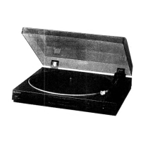
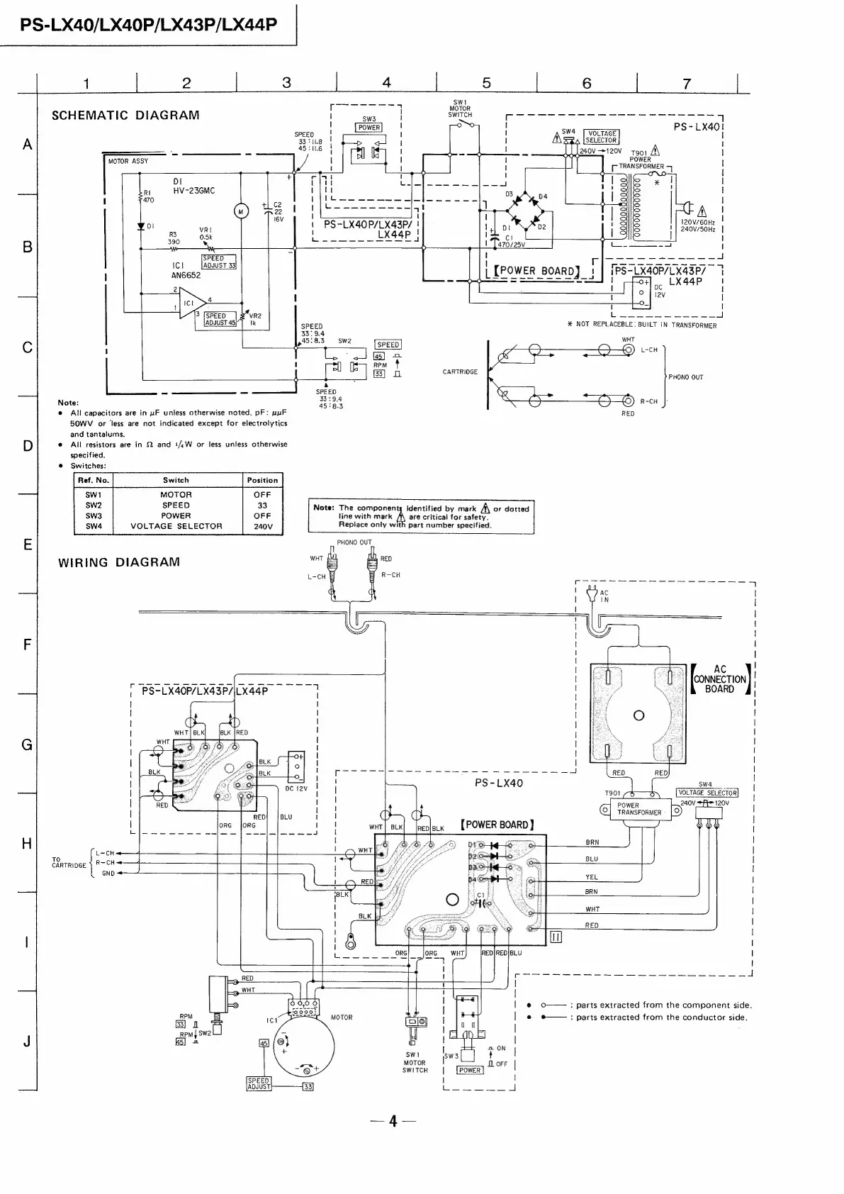
Sony PS-LX40 - Schematic Diagram; Wiring Diagram

Sony PS-LX40
6 pages
Print Icon
To Next Page IconTo Next Page
To Previous Page IconTo Previous Page
Loading...
PS-LX40/LX40P/LX43P/LX44P
1
2
3
Wee
sa,
7
vorar
SCHEMATIC
DIAGRAM
!
Sa
SWITCH
on
ee
ee
7
:
:
PS~LX401
1
i
SW4
[VOLTAGE
A
sae
!
!
|
———
~~
—____
-
i
1
!
240V-*120V
T9091
A\
|
MOTOR
ASSY
|
I
POWER
|
1
1
1
|
Ol
t
j
|
RI
HV-23GMC
|
i
470
t
q
|
A
|
ny
i2ov/6oH2
|
R3
VRI
240V/50H7z
|
B
390
oo
oe
+
~
E
Brae
ad
—---
7
-eOe
Ic!
AdvUST33}
|
0
CL
ee
ee
i
AN6652
PS-LX40P/LX43P/
|
LX44P
>
1
I
.
I
3
SPEED
]2*vR2
|
ft
enn
nn
me
4
%
NOT
REPLACEBLE:
BUILT
IN
TRANSFORMER
1
e
All
capacitors
are
in
uF
unless
otherwise
noted.
pF:
nur
SOWV
or
less
are
not
indicated
except
for
electrolytics
and
tantalums.
D
©
All
resistors
are
in
2
and
#/,W
or
jess
unless
otherwise
specified.
@
Switches:
[rat
Noo
Swich
‘Potion
MOTOR
SPEED
POWER
VOLTAGE
SELECTOR
E
PHONO
OUT
WIRING
DIAGRAM
Note:
The
components
identified
by
mark
A
or
dotted
line
with
mark
A
are
critical
for
safety.
Replace
only
wit
45:8.
pean
ov
mn
©)
a
By
CARTRIOGE
L_
Eo
sa
A
SS
SPEED
:
33:9,4
—DH—O
oer
Note:
45:83
R-CH
RED
Part
number
specified.
AC
iat
AAAI
VAS
BTID
KER
AE.
eee
7
L-CH
«——+4
TO
CARTRIDGE
)
RCH
GND
CONNECTION
BOARD
Sw4
VOLTAGE
SELECTOR
240v
120V
Ele
E)2
bob
w”
s
[Hho
@
O——:
parts
extracted
from
the
component
side.
e
#——-:
parts
extracted
from
the
conductor
side.