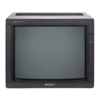
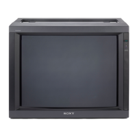
PVM-2530
RM-739
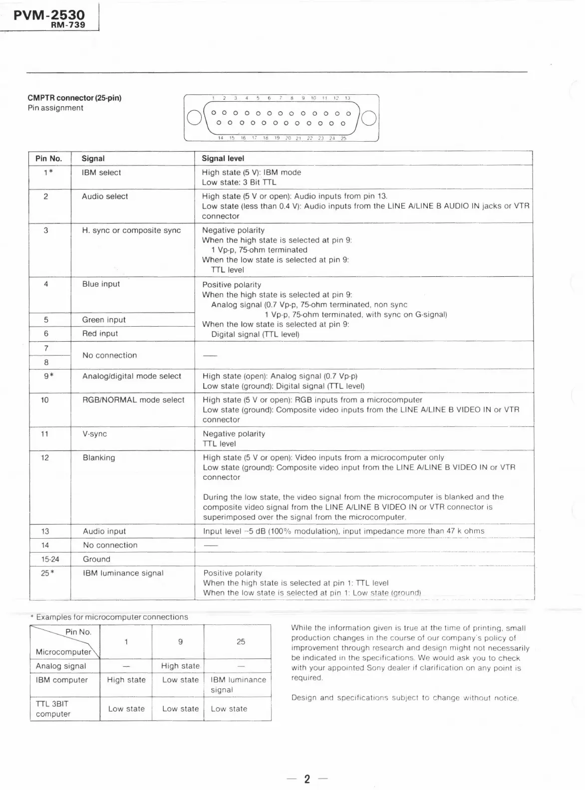
CMPTR connector(25-pin)
Pin assignment
Pin No.
Signal
1 *
IBM select
2
Audio select
3
H. sync or composite sync
4 Blue input
5
Green input
6
Red input
7
No connection
8
9*
Analog/digital mode select
10
RGB/NORMAL mode select
11
V-sync
12
Blanking
13 Audio input
14 No connection
15-24 Ground
25*
IBM luminance signal
0
* Examples for microcomputer connections
::s\
1
9
r
Analog signal - High state
IBM computer High state Low state
TIL 3BIT
Low state Low state
computer
2 3 4 5 6 8 9 10 11 1~ 13
0 0 0 0 0 0 0 0 0 0 0 0 0
0 0 0 0 0 0 0 0 0 0 0 O
14 15 16 17 Hl 19 20 21 22 23 ?J 25
Signal level
High state (5 V): IBM mode
Low state: 3 Bit TIL
0
High state (5 V or open): Audio inputs from pin 13.
Low state (less than 0.4 V): Audio inputs from the LINE A/LINE B AUDIO IN jacks or VTR
connector
Negative polarity
When the high state is selected at pin 9:
1 Vp-p, 75-ohm terminated
When the low state is selected at pin 9:
TIL level
Positive polarity
When the high state is selected at pin 9:
Analog signal (0.7 Vp-p, 75-ohm terminated, non sync
1 Vp-p, 75-ohm terminated, with sync on G-signal)
When the low state is selected at pin 9:
Digital signal (TIL level)
-
High state (open): Analog signal (0.7 Vp-p)
Low state (ground): Digital signal (TIL level)
High state (5 V or open): RGB inputs from a microcomputer
Low state (ground): Composite video inputs from the LINE A/LINE B VIDEO IN or VTR
connector
·-
Negative polarity
TIL level
High state (5 V or open): Video inputs from a microcomputer only
Low state (ground): Composite video input from the LINE A/LINE B VIDEO IN or VTR
connector
During the low state, the video signal from the microcomputer is blanked and the
composite video signal from the LINE A/LINE B VIDEO IN or VTR connector is
superimposed over the signal from the microcomputer.
Input level -5 dB (100% modulation), input impedance more than 47 k ohms
---- ----- - ·--- - -- -
----·-----
-
--- ·--- - - ·-- .
- -· .. --- -- ----- ----- -
-- ---- ---------- - ------- -
Positive polarity
When the high state is selected at pin 1: TIL level
-----1
When the low state is selected at pin 1: Low state (ground)
25
-
IBM luminance
signal
Low state
-· -- - - - -- --- --
While the information given is true at the time of printing . small
production changes in the course of our company"s policy of
improvement through research and design might not necessarily
be indicated in the specifications . We would ask you to check
with your appointed Sony dealer if clarification on any point is
required.
Design and specificati ons subJect to change without notice .
- 2 -
 Loading...