UFOELK - 2/21/2018 5:23 PM
HT-RT3
13
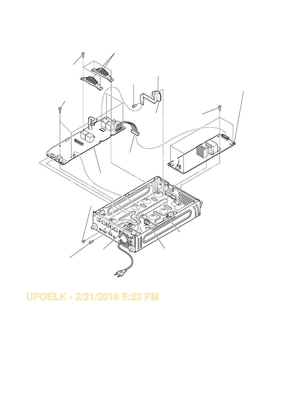
2-7. MAIN BOARD, CONNECTOR BOARD, SWITCHING REGULATOR
A
A
1 wire (flat type) (20 core) (CN2006)
0 one screw
(+BV3 (3-CR))
4 one screw (+BV3 (3-CR))
qa CONNECTOR
board
2 CN101 (9P)
5 one screw (+B 3 x 5)
8 four screws
(+BVTP 3 x 8)
qd four screws
(+BVTP 3 x 8)
qf Remove REGULATOR,
SWITCHING 3L405W-2 (EXCEPT E12) /
REGULATOR, SWITCHING 3L405W-3 (E12)
from holder, PC board.
3 CN3200 (2P)
qs CN1 (2P)
qg REGULATOR, SWITCHING 3L405W-2 (EXCEPT E12) /
REGULATOR, SWITCHING 3L405W-3 (E12)
6 four screws
(+BVTP 3 x 8)
9 MAIN board
7 heat sink (EL-SW)
Note: When installing the heat sink (EL-SW), spread the compound referring to
"NOTE OF REPLACING THE IC1000 AND IC1002 ON THE MAIN BOARD
AND THE COMPLETE MAIN BOARD " on page 5.
– Rear view –
Ver. 1.1
• Abbreviation
E12 : 220-240 V AC area in E model