HT-RT3
6
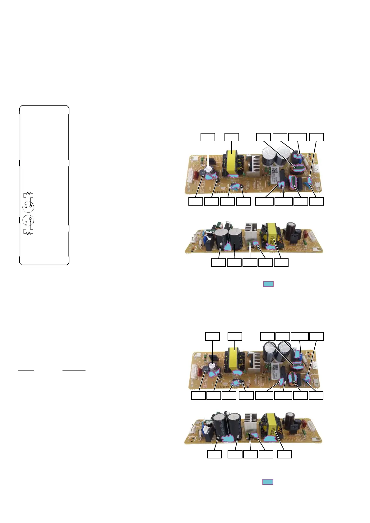
CAPACITOR ELECTRICAL DISCHARGE PROCESSING
When checking the board, for the electric shock prevention, con-
nect the resistors to both ends of respective capacitor (C201 and
C207) to discharge the capacitor (C201 and C207).
C207
C201
800 :/2 W
800 :/2 W
- REGULATOR, SWITCHING 3L405W-2 Board
(EXCEPT E12) (Conductor Side) -
- REGULATOR, SWITCHING 3L405W-3 Board
(E12) (Conductor Side) -
BOND FIXATION OF ELECTRIC PARTS
When REGULATOR, SWITCHING 3L405W-2 board (Except
E12), REGULATOR, SWITCHING 3L405W-3 board (E12) or
MAIN board is replaced, it is necessary to fi x parts to the boards
by using a specifi ed bond without fail.
• Object boards
1. REGULATOR, SWITCHING 3L405W-2 board (Except
E12)
2. REGULATOR, SWITCHING 3L405W-3 board (E12)
3. MAIN board
• Use bond
Part No. Description
7-600-020-70 ADHESIVE (SC608Z2) 180ML
• Parts position
1. REGULATOR, SWITCHING 3L405W-2 board (Except
E12) (page 6)
2. REGULATOR, SWITCHING 3L405W-3 board (E12)
(page 6)
3. MAIN board (page 7)
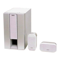
1. REGULATOR, SWITCHING 3L405W-2 board (Except
E12)
C402 T201
C102
NR101
TH101 RC201
L101
L401 C461 C215 C204
C207 C211 T201R208C201
L102 C103
C101
*
The portion which applies bond:
– REGULATOR, SWITCHING 3L405W-2 Board
(EXCEPT E12) (Component Side) –
2. REGULATOR, SWITCHING 3L405W-3 board (E12)
C402 T201 C101 C102
C103C204
C201 C207 C211 T201R208
C215C461L401
L101
L102
NR101
RC201TH101
*
The portion which applies bond:
– REGULATOR, SWITCHING 3L405W-3 Board
(E12) (Component Side) –