SDM-S71 (E) 3-10
1
A
B
C
D
E
F
G
H
I
2
12
13
11
10
98765
43
14
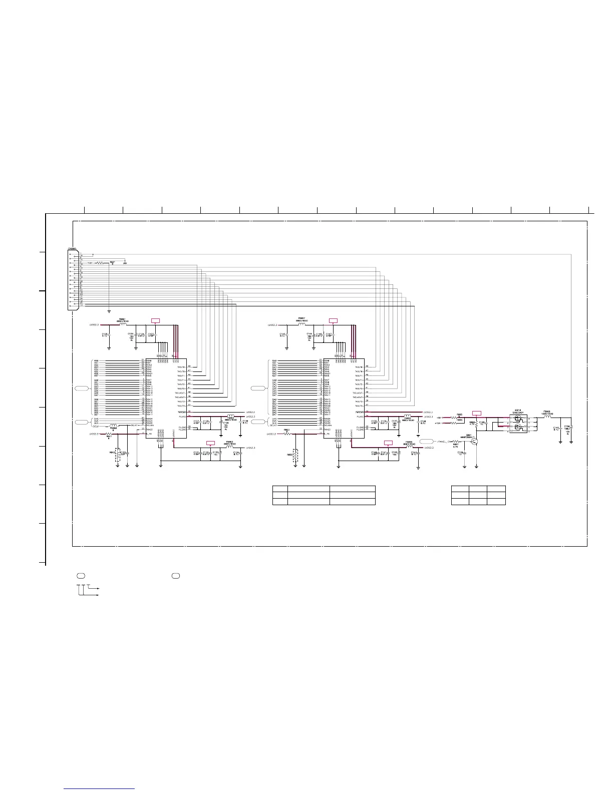
• Divided circuit diagram
One sheet of INTERFACE board circuit diagram is divided into six sheets,
each having the code INTERFACE-a to INTERFACE-f. For example, the destination
ab1 on the code INTERFACE-a sheet is connected to ab1 on the INTERFACE-b sheet.
a b 1
Ref. No.
Circuit diagram division code
+3.3V
+3.3V
+3.3V
+5V
+3.3V
INTERFACE-e
(DISPLAY)
B-SS3628<J..> - INTERFACE-P5
#
#
R_FV
R53
R55
17"
18"
R065
V
X
R066
V
X
Rising edge strobe
V
X
Falling edge strobe
V
X
#
IC016
DS90C385
LVDS
IC017
DS90C385
LVD S
ce14
ce12
ce13
ce12
cf19
TO
PANEL