SDM-S71 (E) 3-11
1
A
B
C
D
E
F
G
H
I
2
12
13
11
10
98765
43
14
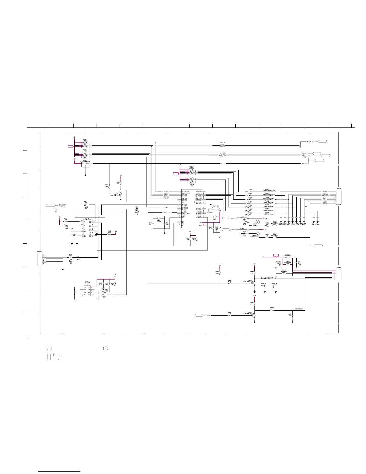
• Divided circuit diagram
One sheet of INTERFACE board circuit diagram is divided into six sheets,
each having the code INTERFACE-a to INTERFACE-f. For example, the destination
ab1 on the code INTERFACE-a sheet is connected to ab1 on the INTERFACE-b sheet.
a b 1
Ref. No.
Circuit diagram division code
+5V
+5V
+12V
INTERFACE-f
(MCU)
B-SS3628<J..> - INTERFACE-P6
cf11
cf2
cf7
cf6
cf10
cf9
ef19
af1
cf8
bf3
IC201
89C738
MCU
TO
H BOARD
CN010
TO
INVERTOR
EEPROM