EasyManua.ls Logo

Sony SLV-495 - General Setup Information

Sony SLV-495
61 pages
Print Icon
To Next Page IconTo Next Page
To Previous Page IconTo Previous Page
Loading...
40
|
Additional
Information
General
setup
information
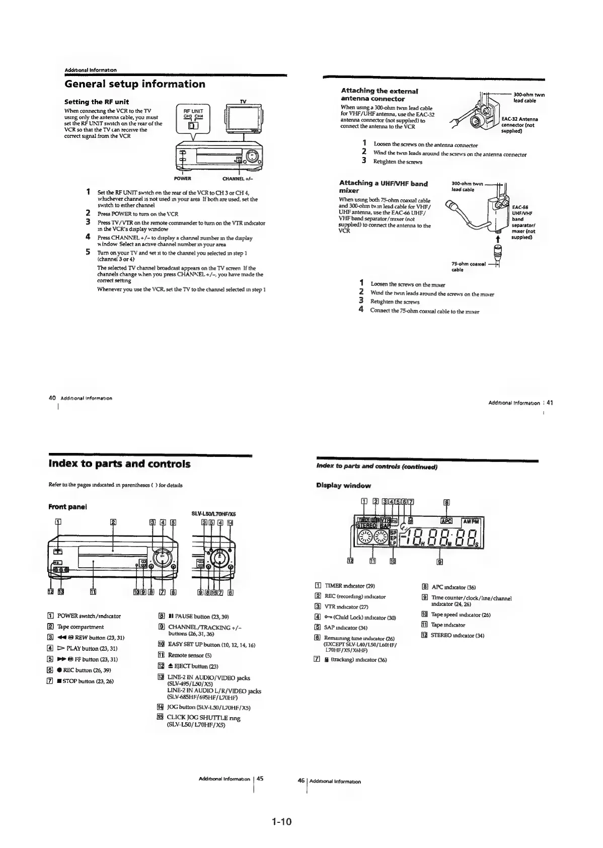
Setting
the
RF
unit
When
connecting
the
VCR
to
the
TV
RF
UNIT
using
only
the
antenna
cable,
you
must
Gas
Cue
set
the
RF
UNIT
swatch
on
the
rear
of
the
VCR
so
that
the
TV
can
receive
the
correct
signal
from
the
VCR
POWER
CHANNEL
+/-
1
Set the
RF
UNIT
switch
on
the
rear
of
the
VCR
to
CH
3
or
CH
4,
whichever
channel
1s
not
used
in
your
area
If
both
are
used,
set
the
switch
to
either
channel
Press
POWER
to
turn
on
the
VCR
Press
TV/VTR
on
the
remote
commander
to
turn
on
the
VIR
indicator
in
the
VCR's
display
window
Press
CHANNEL
+/-
to
display
a
channel
number
in
the
display
window
Select
an
active
channel
number
in
your
area
Turn
on
your
TV
and
set
:t
to
the
channel
you
selected
in
step
1
(channel
3
or
4)
The
selected
TV
channel
broadcast
appears
on
the
TV
screen
If
the
channels
change
when
you
press
CHANNEL
+/-,
you
have
made
the
correct
setting
Whenever
you
use
the
VCR,
set
the
TV
to
the
channel
selected
in
step
1
uu
fF
WN
Additional
information
I
FS
2
a
I
I
ES
Index
to
parts
and
controls
Refer
to
the
pages
indicated
in
parentheses
( )
for
details
ea]
2
(3)
(4)
5)
&
[7]
SLV-LS5O/L70HF/X5
POWER
switch/indicator
1
PAUSE
button
(23,
39)
Tape
compartment
CHANNEL/TRACKING
+/-
buttons
(26,
31,
36)
44
&
REW
button
(23,
31)
{19
EASY
SET
UP
button
(10,
12,
14,
16)
[>
PLAY
button
(23,
31)
ff}
Remote
sensor
(5)
b>
&
FF
button
(23,
31)
EJECT
button
(23)
@
REC
button
(26,
39)
[fJ
LINE-2
IN
AUDIO/VIDEO
jacks
@
STOP
button
(23,
26)
(SLV-495
/L50/X5)
LINE-2
IN
AUDIO
L/R/VIDEO
jacks
(SLV-685HF/695HF/L70HF)
(14
JOG
button
(SLV-L50/L70HF/X5)
{|
CLICK
JOG
SHUTTLE
ring
(SLV-L50/L70HF/
X5)
Additional
Information
|
45
1-10
LL
aA
re
RS
a
Attaching
the
external
antenna
connector
When
using
a
300-ohm
twin
lead
cable
for
VHF/UHF
antenna,
use
the
EAC-32
antenna
connector
(not
supplied)
to
connect
the
antenna
to
the
VCR
300-ohm
twin
lead
cable
EAC-32
Antenna
connector
(not
supphed)
1
Loosen
the
screws
on
the
antenna
connector
2
Wing
the
twin
leads
around
the
screws
on
the
antenna
connector
3
Retighten
the
screws
Attaching
a
UHF/VHF
band
300-ohm
twin
mixer
lead
cable
When
using
both
75-ohm
coamal
cable
and
300-ohm
twin
Jead
cable
for
VHF/
UHF
antenna,
use
the
EAC-66
UHF/
VHF
band
separator/mxer
(not
supphed)
to
connect
the
antenna
to
the
VCR
EAC-66
UHF/VHF
band
separator/
mixer
(not
t
supplted)
75-ohm
coaxial
cable
Loosen
the
screws
on
the
mixer
Wind
the
twin
leads
around
the
screws
on
the
mixer
Retighten
the
screws
PWNh
Connect
the
75-ohhm
coaxial
cable
to
the
mixer
Additional
Information
|
41
i
Index
to
parts
and
controls
(continued)
Display
window
(1)
TIMER
indicator
(29)
[B}
APC
indicator
(36)
[2]
REC
(recording)
indicator
[9]
Time
counter/clock/line/channel
indicator
(24,
26)
(3)
VTR
indicator
(27)
[4]
o
(Child
Lock)
indicator
(30)
(5)
SAP
indicator
(34)
[6]
Remaining
time
indicator
(26)
(EXCEPT
SLV-L40/L50/L60HF/
L70HF/X5/X6HF)
&
(tracking)
indicator
(36)
(0
Tape
speed
indicator
(26)
fi)
Tape
indicator
ff]
STEREO
indicator
(34)
46
|
Additional
Information

Table of Contents