SRF-18
4
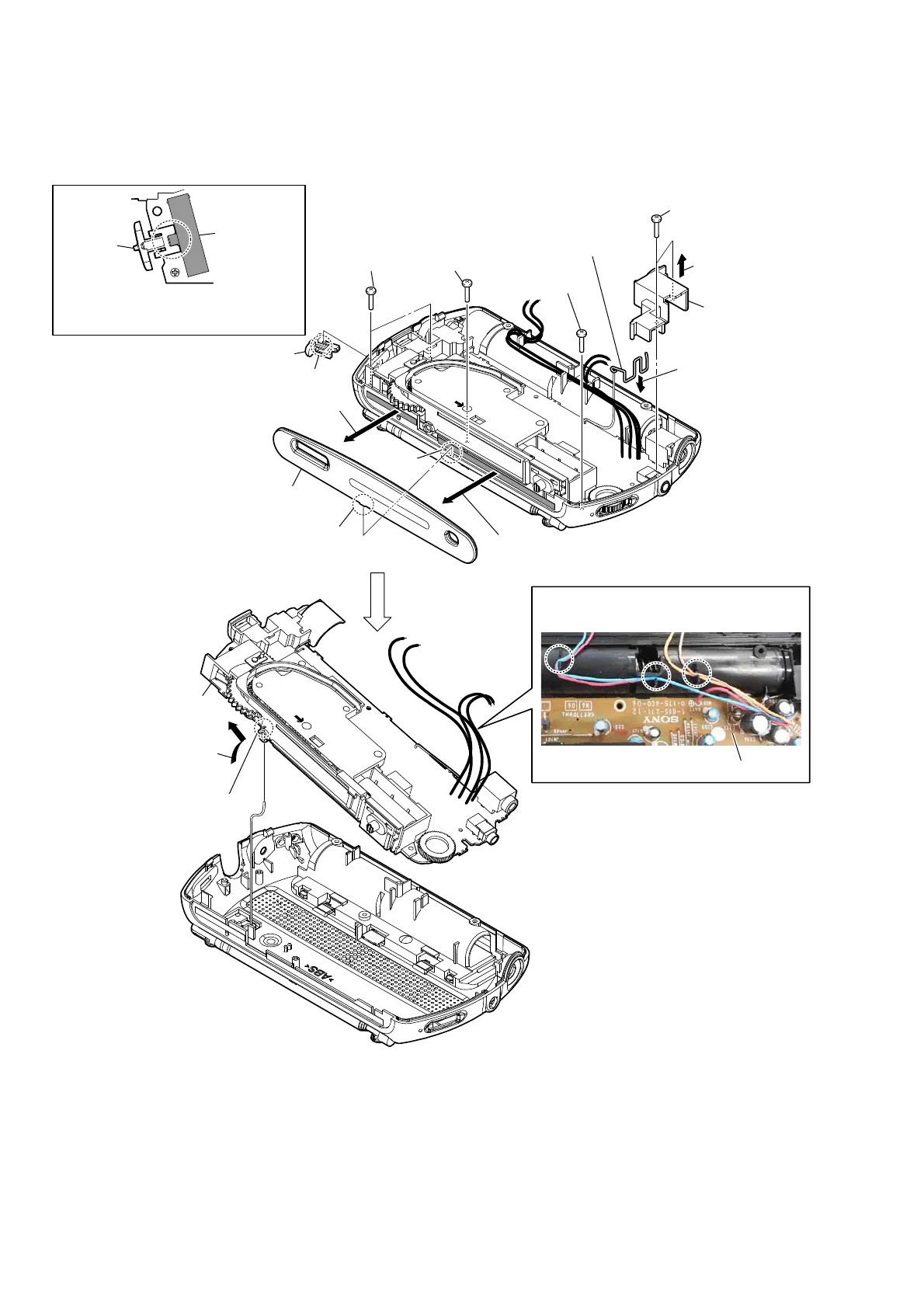
qa MAIN board block
5 two screws
(1.7)
5 two screws
(1.7)
5 screw (1.7)
5 screw (1.7)
– Front top view –
– Front top view –
2 knob (power) block
8 holder
(headphone)
battery terminal (+)
4 transparent plate
1 two claws
9 Remove the solder.
MAIN board
:ire VettinJ
6 Lift up the holder
(headphone) block.
3 Peel off the transparent plate
from adhesive sheet.
3 Peel off the transparent plate
from adhesive sheet.
7 Remove the battery
terminal (+) in the
direction of an arrow.
0 Lift up the MAIN board block
in the direction of an arrow.
knob
(power)
switch
(S501)
Note: When installing the knob (power),
the position of switch (S501) and
claw of knob (power) is set and installed.
Note: When installing the transparent plate, the position of
convex part and ditch is set and installed.
ditch
1-3. MAIN BOARD BLOCK