EasyManua.ls Logo

Sony SRF-18 Service Manual

Sony SRF-18
16 pages
To Next Page IconTo Next Page
Page #1 background imageLoading...
Page #1 background image
SERVICE MANUAL
Sony Corporation
Published by Sony Techno Create Corporation
SRF-18
SPECIFICATIONS
FM STEREO/AM RADIO
9-893-410-02
2012C33-1
©
2012.03
E Model
Ver. 1.1 2012.03
Frequency range:
FM: 87.5 MHz - 108 MHz
AM: 530 kHz - 1,710 kHz
Speaker:
Approx. 3.6 cm (1
7
/
16
inches) dia, 7.2 (2)
Input:
AUDIO IN jack (
3.5 mm stereo minijack) (1)
Outputs:
(headphones) jack ( 3.5 mm stereo minijack) (1)
AUDIO OUT jack (
3.5 mm stereo minijack) (1)
Power output:
80 mW + 80 mW (JEITA*)
Power requirements:
3 V DC, two size AA (R6) batteries
Dimensions:
Approx. 155 mm × 78.5 mm × 32.5 mm (6
1
/
8
inches × 3
1
/
8
inches × 1
5
/
16
inches)
(w/h/d, projecting parts not included)
Approx. 155.4 mm × 80.3 mm × 34.2 mm (6
1
/
8
inches × 3
1
/
4
inches × 1
3
/
8
inches)
(w/h/d, projecting parts included)
(JEITA*)
Mass:
Approx. 198 g (7 oz) (batteries included)
* JEITA (Japan Electronics and Information Technology Industries Association) standards.
Supplied accessories
Operating Instructions (1)
Audio connecting cable (stereo mini plug
stereo mini plug) (1)
Design and specications are subject to change without notice.
On Copyrights
“WALKMAN” and “WALKMAN” logo are registered trademarks of Sony
Corporation.
NOTES ON CHIP COMPONENT REPLACEMENT
Never reuse a disconnected chip component.
Notice that the minus side of a tantalum capacitor may be dam-
aged by heat.
UNLEADED SOLDER
Boards requiring use of unleaded solder are printed with the lead-
free mark (LF) indicating the solder contains no lead.
(Caution: Some printed circuit boards may not come printed with
the lead free mark due to their particular size)
: LEAD FREE MARK
Unleaded solder has the following characteristics.
Unleaded solder melts at a temperature about 40 °C higher
than ordinary solder.
Ordinary soldering irons can be used but the iron tip has to be
applied to the solder joint for a slightly longer time.
Soldering irons using a temperature regulator should be set to
about 350 °C.
Caution: The printed pattern (copper foil) may peel away if
the heated tip is applied for too long, so be careful!
• Strong viscosity
Unleaded solder is more viscous (sticky, less prone to ow)
than ordinary solder so use caution not to let solder bridges
occur such as on IC pins, etc.
Usable with ordinary solder
It is best to use only unleaded solder but unleaded solder may
also be added to ordinary solder.

Other manuals for Sony SRF-18

Question and Answer IconNeed help?

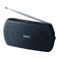
Do you have a question about the Sony SRF-18 and is the answer not in the manual?

Sony SRF-18 Specifications

Frequency Range IconFrequency Range
FM frequency range87.5 MHz - 108 MHz
AM frequency range530 kHz - 1 710 kHz
Speaker IconSpeaker
speaker diameter3.6 cm
speaker impedance7.2 Ω
output power80 mW + 80 mW
Power IconPower
power supply voltage3 V DC
battery typetwo R6 (size AA) batteries
weight with batteries198 g
Ports & Interfaces IconPorts & Interfaces
audio input port3.5 mm stereo mini-jack
headphone output port3.5 mm stereo mini-jack
audio output port3.5 mm stereo mini-jack
Dimensions IconDimensions
dimensions without protrusions155 mm × 78.5 mm × 32.5 mm
dimensions with protrusions155.4 mm × 80.3 mm × 34.2 mm

Summary

Specifications

Disassembly Procedure

Disassembly Flow Chart

Outlines the step-by-step process for disassembling the set.

Front Cabinet Disassembly

Detailed steps for removing the front cabinet section of the unit.

Main Board Block Disassembly

Procedure for accessing and removing the main board block assembly.

Main Board Removal

Instructions for detaching and removing the main board component.

Knob and Gear Disassembly

Steps for removing the tune knob and gear (VC) components.

Electrical Adjustment Procedures

FM Adjustments

Covers FM 2ND OSC, frequency coverage, tracking, and VCO adjustments.

AM Adjustments

Covers AM frequency coverage and tracking adjustments.

Diagrams and Schematics

Printed Wiring Board Diagrams

Illustrates the physical layout of components on the printed circuit boards.

Schematic Diagrams

Detailed circuit diagrams showing electronic component connections.

IC Block Diagrams

High-level functional block diagrams for integrated circuits used in the device.

Exploded Views of Components

Front Cabinet Exploded View

Detailed breakdown of parts for the front cabinet section.

Chassis Exploded View

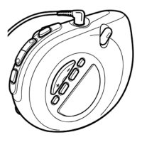
Exploded illustration of the internal chassis and its components.

Rear Cabinet Exploded View

Breakdown of parts for the rear cabinet assembly.

Electrical Parts List

Revision History

Related product manuals