SRF-18
SRF-18
77
SECTION 2
ELECTRICAL ADJUSTMENTS
0 dB = 1 V
FM 2ND OSC ADJUSTMENT
Refer to the connecting location and adjustment location.
Setting:
Band: FM
unit
MAIN board
TP (GND)
MAIN board
TP (DET)
MAIN board
TP (FM IN)
MAIN board
TP
(FM 2ND OSC)
FM RF signal
generator
Carrier frequency:
98 MHz
Modulation:
no modulation
Output level:
100 dBPV (100 mV)
0.01 PF
1 PF
10 PF
Frequency
conunter
+
+
Procedure:
1. Connect the frequency counter to TP (FM 2ND OSC) as shown
the fi gure.
2. Tune the unit to 98 MHz.
3. Adjust L102 so that the reading is set to standard value on
frequency counter.
Standard value : 56.5 to 57.0 MHz
[AM]
Setting:
Band: AM
Volume: max
AM RF signal
generator
30% amplitude modulation by 400Hz
signal.
Output level : as low as possible
Put the lead-wire
antenna close to
the set.
[FM]
Setting:
Band: FM
Volume: max
unit
MAIN board
TP (GND)
MAIN board
TP (FM IN)
FM RF signal
generator
22.5 kHz frequency
deviation by
400Hz signal
Output level : as
low as possible
0.06 PF
16 :
+
–
i jack (J201)
level meter
• Repeat the procedures in each adjustment several times, and
the tracking adjustments should be fi nally done by the trimmer
capacitors.
• Remove FM antenna in FM adjustment.
Refer to the connecting location and adjustment location.
AM FREQUENCY COVERAGE ADJUSTMENT
Adjust for a maximum reading on level meter.
L103 520 kHz
CT101-4 1750 kHz
AM TRACKING ADJUSTMENT
Adjust for a maximum reading on level meter.
L105 620 kHz
CT101-3 1400 kHz
FM FREQUENCY COVERAGE ADJUSTMENT
Adjust for a maximum reading on level meter.
L106 86.5 MHz
CT101-1 109.5 MHz
FM TRACKING ADJUSTMENT
Adjust for a maximum reading on level meter.
L101 86.5 MHz
CT101-2 109.5 MHz
FM VCO ADJUSTMENT
Refer to the connecting location and adjustment location.
Setting:
Band: FM
unit
MAIN board
TP (GND)
MAIN board
TP (DET)
MAIN board
TP (FM IN)
MAIN board
TP (VCO)
FM RF signal
generator
Carrier frequency:
98 MHz
Modulation:
no modulation
Output level:
100 dBPV (100 mV)
0.01 PF
1 PF
10 PF
Frequency
conunter
+
+
Procedure:
1. Connect the frequency counter to TP (VCO) as shown the fi g-
ure.
2. Tune the unit to 98 MHz.
3. Adjust L104 so that the reading is set to standard value on
frequency counter.
Standard value : 37.95 to 38.05 kHz
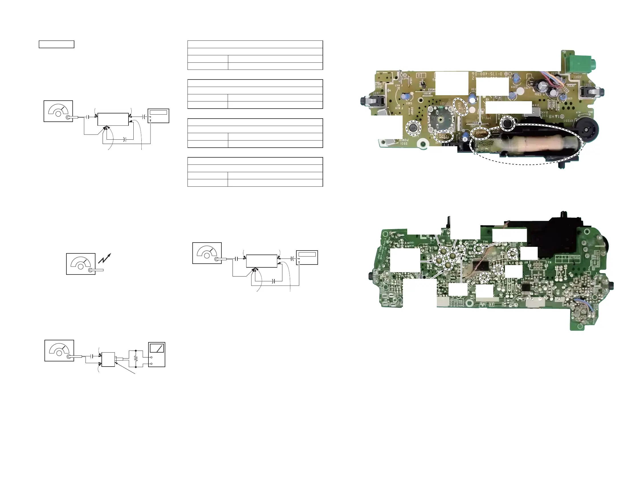
Connectiong and adjustment location:
– MAIN Board (Component Side) –
– MAIN Board (Conductor Side) –
L104
FM VCO adjustment
L102
FM 2ND OSC
adjustment
L106
FM frequency
coverage
adjustment
L103
AM frequency
coverage
adjustment
CT101-4
(AM OSC)
AM frequency
coverage
adjustment
CT101-1
(FM OSC)
FM frequency
coverage
adjustment
L101
FM tracking
adjustment
L105
AM tracking
adjustment
CT101-3
(AM ANT)
AM tracking
adjustment
CT101-2
(FM ANT)
FM tracking
adjustment
TP
(DET)
TP
(GND)
TP
(VCO)
TP
(FM 2ND OSC)
TP
(FM IN)