– 37 –
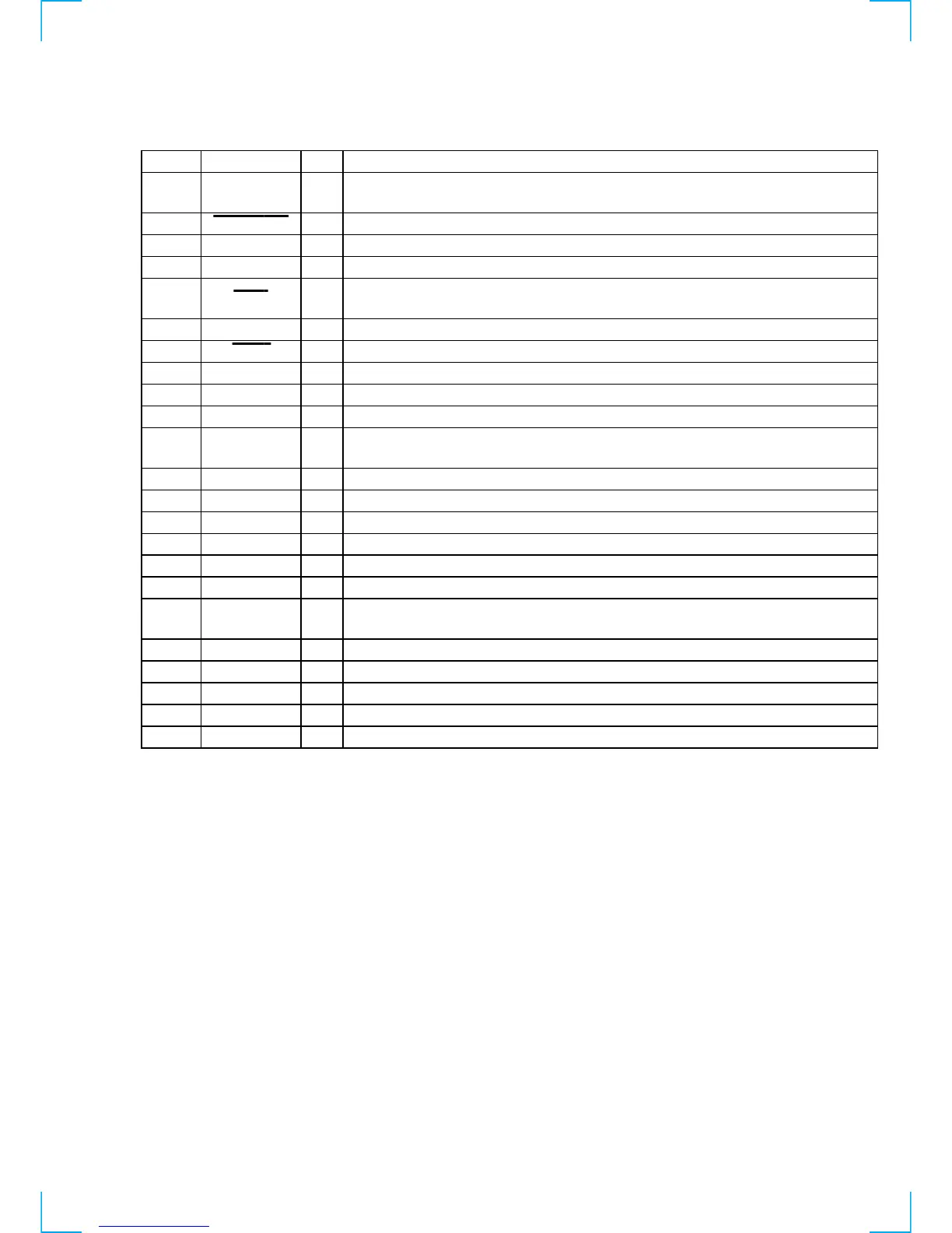
Pin No. Pin Name I/O Description
43
VOL UP O
Motor drive signal (volume up direction) output to the volume motor drive (IC202)
“H” active
44
SYS-POWER I
Power on/off switch (S200 I/u) input terminal “L” is input when key pressing
45 TUNER-MUTE
O Muting control signal output to the FM/AM tuner pack “H”: muting on
46
RDS CLK IN I RDS serial clock signal input from the RDS decoder (IC1)
47
STOP I
Power down detection signal input from the reset signal generator (IC950)
“L”: power down, normally: “H”
48
VSS — Ground terminal
49
SIRCS I Sircs remote control signal input from the remote control receiver (IC203)
50
MUTING LED O LED drive signal output of the MUTING indicator (D240) “L”: LED on
51
5.1CH LED O LED drive signal output terminal “L”: LED on Not used
52
VDD — Power supply terminal (+5V)
53
BASS BOOST O
Control signal output of the BASS BOOST circuit and LED drive signal output of the BASS
BOOST indicator (D228) “H”: BASS BOOST on (LED on)
54
FUNC. MUTE O Audio line muting on/off control signal output terminal “H”: muting on
55
IC. MUTE O Muting on/off control signal output terminal “H”: muting on Not used (open)
56
VERSION I Setting terminal for the version
57
S2 O Video input select signal output terminal Not used (pull down)
58
S1 O Video input select signal output terminal Not used (pull down)
59
LED1 O LED drive signal output of the CENTER (D233) and REAR (D237) indicators “H”: LED on
60
LED2 O
LED drive signal output of the NAME (D235) and EFFECT/DELAY (D236) indicators
“H”: LED on
61
LED3 O LED drive signal output of the SET UP (D234) indicator “H”: LED on
62 to 70
S15 to S7 O Segment drive signal output to the fluorescent indicator tube (FL201)
71
VLOAD — Negative power supply terminal for the fluorescent indicator tube drive (–24V)
72 to 77
S6 to S1 O Segment drive signal output to the fluorescent indicator tube (FL201)
78 to 80
DIG10 to DIG8 O Digit drive signal output to the fluorescent indicator tube (FL201)