14
The output audio signal can be changed under
“Audio Preset” (page 27) in the “User Preset
Setting” menu.
ENHANCED MONITOR OUT connector
Used for future expansion. It is currently
unavailable.
SDI OUT (SDI output) connectors (BNC)
Output connectors for serial digital signals.
The signal input to the SDI IN connector
corresponding to the to is output.
SDI output is not activated when the unit is
turned off or in sleep mode.
If a 12G-SDI or 6G-SDI signal is output from the
SDI OUT connector, a 12G-SDI cable (L-5.5CUHD
manufactured by Canare Electric Co., Ltd. or an
equivalent) is recommended.
SDI IN (SDI input) connectors (BNC)
Input connectors for serial digital signals.
For details, see “Connecting the SDI Signals”
(page 14).
If a 12G-SDI or 6G-SDI signal is input to the SDI IN
connector, a 12G-SDI cable (L-5.5CUHD
manufactured by Canare Electric Co., Ltd. or an
equivalent) is recommended.
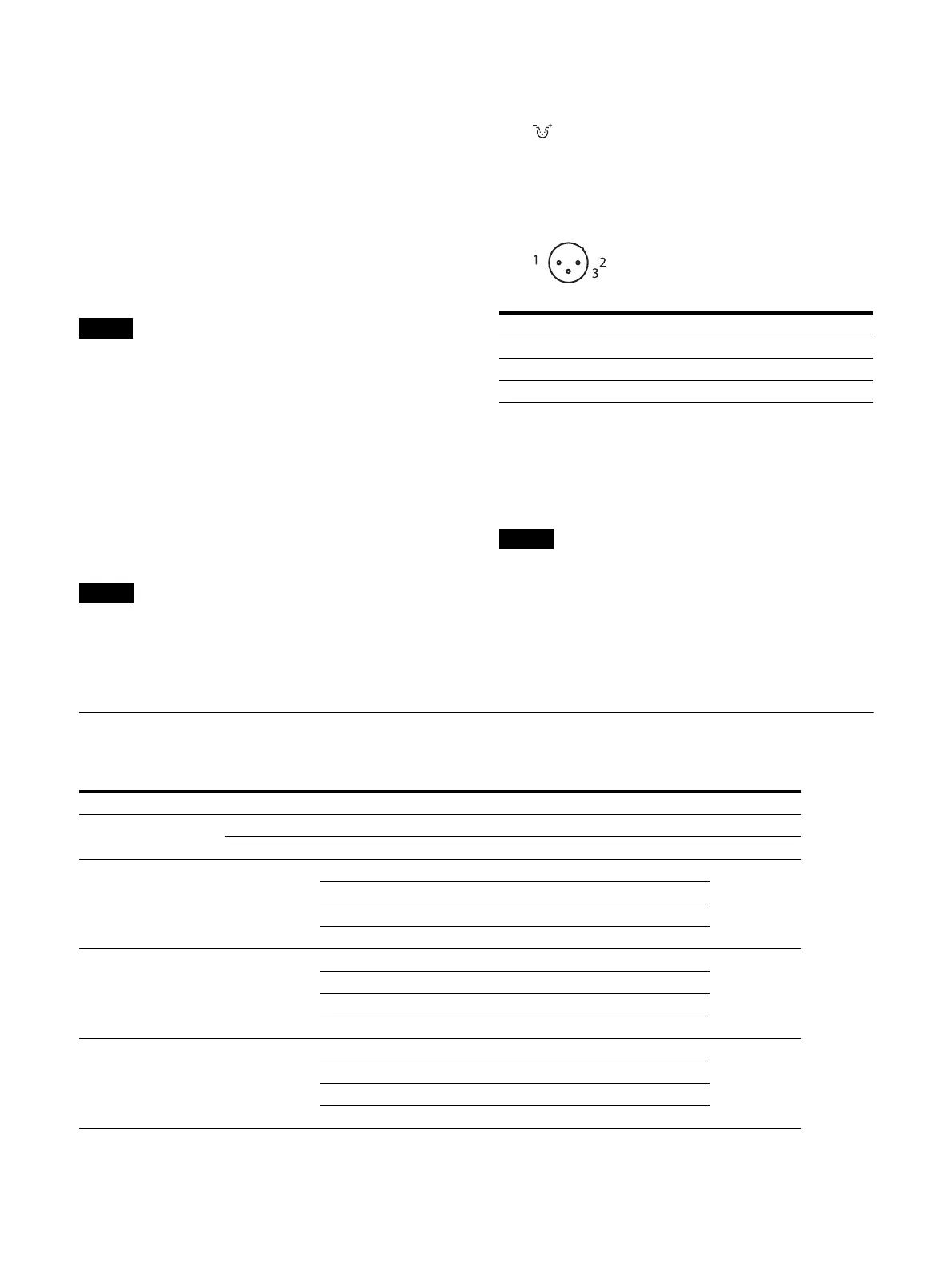
DC IN 22 to 32 V (DC power input)
connector
Connect to a DC 22 V to 32 V DC power supply.
Pin assignment (Rear of monitor)
AC IN socket
Connect the supplied AC power cord.
Main power switch
Press to turn on the unit.
If a no input-signal state continues for 60
minutes, the monitor is automatically turned off
by the auto power-off function. To turn on the
monitor, press the (Power) switch. To change
the settings, see “Auto Power Down” (page 38) of
“System Setting” in the “System” menu.
Connecting the SDI Signals
The following signals can be input to the SDI IN connectors of this unit.
Pin number Functions
1– (GND)
2 + (DC 22 V to 32 V)
3NC
Input signal Connector Maximum
Single Link 3G/HD-SDI - 1 to 4 4 channels
12G/6G-SDI - 1, 3 2 channels
Dual Link 3G/HD-SDI
3G/HD-SDI Link 1 1
2 channels
3G/HD-SDI Link 2 2
3G/HD-SDI Link 1 3
3G/HD-SDI Link 2 4
Quad Link
(2-sample interleave
division)
3G/HD-SDI
3G-SDI Link 1 1
1 channel
3G-SDI Link 2 2
3G-SDI Link 3 3
3G-SDI Link 4 4
Quad Link
(Square division)
3G/HD-SDI
Mapping signal of Sub image 1 (upper-left screen) 1
1 channel
Mapping signal of Sub image 2 (upper-right screen) 2
Mapping signal of Sub image 3 (lower-left screen) 3
Mapping signal of Sub image 4 (lower-right screen) 4
 Loading...