20
• When complete readjustment is necessary or a new picture tube is
installed, carry out the following adjustments.
• Unless there are specific instructions to the contrary, carry out
these adjustments with the rated power supply.
• Unless there are specific instructions to the contrary, set the
controls and switches to the following settings :
Contrast .................................. normal
Brightness .................................. normal
Preparation :
1. In order to reduce the influence of geomagnetism on the set’s
picture tube, face it in an easterly or westerly direction.
2. Switch on the TV set’s power and degauss with a degausser.
(1) Adjustment of Correction Magnet for Y-Splitting Axis.
1. Input a crosshatch signal from the pattern generator.
2. Set the Picture control to minimum and confirm that the
Brightness control is set to normal.
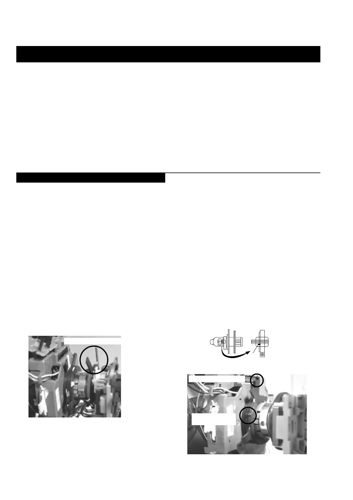
3. Position the neck assembly as indicated in Fig.3-2.
4. Loosen the deflection yoke fixing screw.
5. Move the deflection yoke as far forward as is possible.
6. Adjust the upper and lower pin symmetrically by opening or
closing the Y-splitting axis correction magnets located on the neck
assembly.
7. Return the deflection yoke to its original position and re-tighten its
fixing screw.
Carry out the adjustments in the following order :
3-1. Beam Landing.
3-2. Convergence.
3-3. Focus.
3-4. White Balance.
Note : Test equipment required.
1. Color bar/pattern generator.
2. Degausser.
3. Oscilloscope.
4. Digital multimeter.
Fig.3-1
(2) Landing
Note : Before carrying out the following adjustments adjust the
magnets as indicated below [See Fig.3-3].
1. Input an all-white signal from the pattern generator.
Maximize the picture setting and adjust the Brightness setting.
2. Rough-adjust the focus and horizontal convergence.
3. Loosen the deflection yoke screws and align the purity adjustment
knob to its central position. [See Fig.3-3].
4. Switch from the all-white pattern to an all-green pattern.
5. Move the deflection yoke backwards and adjust with the purity
magnet so that the green is at the centre and it aligns
symmetrically [See Fig.3-4].
6. Move the deflection yoke forward and adjust so that the entire
screen becomes green.
7. Switch the raster signal to red, then to blue and verify the landing
condition.
8. When the position of the deflection yoke has been determined,
fasten the deflection yoke with its fixing screw.
9. If the beam does not land correctly in all the corners of the screen,
use magnets to correct it.
SECTION 3 SET-UP ADJUSTMENTS
3-1. Beam Landing
Caution :
High voltages are present on the Deflection yoke terminals - take care
when handling the Deflection yoke whilst carrying out adjustments.
Y-splitting axis correction magnet
Purity magnets
Align pips on
each magnet
Fig.3-3
Align both Purity magnets
to the vertical position
Neck assy
Align the bottom edge
of the neck assy with
the G3 hole centre
Fig.3-2