28
V SIZE
V LIN
AFC V BOW
V POS
H POS
H SIZE
H PIN CUSH
H TILT
H UP COR
AFC V ANGLE
H LOWER COR
Same Level
B-Out Waveform
noitcelfeD
oNrcseDfeDniMxaMataD
1eziS-V1303624
2noitisoP-V1303613
3pmoC-V1031
4raeniL-V70518
5rroC-S70518
6eziS-H1303655
7CD-WEFFOFFONOFFO
82miTbkAFFOFFONOFFO
9pmA-niP1303634
01pmoC-H0030
11nipC-pU1303613
21niP-M2032
31niPC-oL1303683
41muizeparT70514
51noitisoP-H1303652
61wKlbV0030
71woB-CFA70516
81elgnA-CFA70518
91klB-tfeL2503625
02klB-thgiR1103611
12nureerF-V0030
22tcepsA-V00360
32wS-mooZFFOFFONOFFO
42nacS-UFFOFFONOFFO
52llorcS-V1303613
62miT-bkA2032
72nilV-pU00510
82nilV-oL00510
92pmAPPIPM5-01-011-
03niPCUPIPM001-012
13niPCLPIPM001-010
23parTPIPM001-011
33pmAPGPE3-01-016-
43niPCUGPE001-013-
53niPCLGPE101-011-
63parTGPE001-011-
Table.4-11
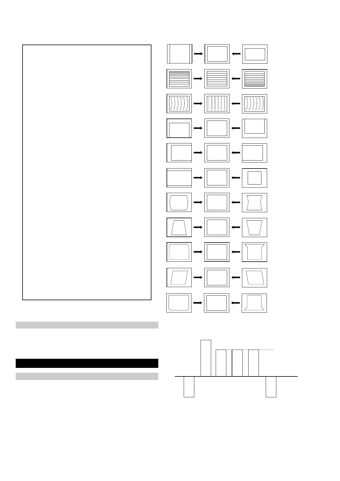
1. Enter into the service mode and select ‘Deflection’ from the
menu. The ‘Deflection’ adjustment menu will be displayed.
2. Select and adjust each item to obtain the optimum image.
4-2. Volume Electrical Adjustments
Deflection System Adjustment
Sub Colour Adjustment
1. Input a PAL colour bar signal.
2. Connect an oscilloscope to CN5400 pin 5 located on the C Board.
3. Enter into the ‘Service Mode’.
4. Choose ‘Backend’ from the menu.
5. Adjust ‘Sub Colour’ data so that the right sides of the waveform
are of equal height.