— 12 —
KV-32HS20/36HS20/36HS20H/32XBR450/36XBR450/36XBR450H
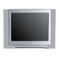
2-3.4. SCREEN-CORNER CONVERGENCE
Preparation:
• Input a cross hatch pattern signal.
1. Affi x a permalloy assembly corresponding to the misconverged areas:
d
c
a
b
a-d: screen-corner
misconvergence
a
b
c
d
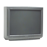
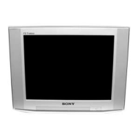
2-3.5. DYNAMIC CONVERGENCE
ADJUSTMENTS
Set dynamic convergence using the following service mode adjustment
data:
NO. Register Function Data Length Initial Data
1 YBWU VCA9 0-63 31
2 YBWL VCA10 0-63 31
3 RSAP DC-AMP1 0-63 31
4 RUBW VCA5 0-63 31
5 RLBW VCA6 0-63 31
6 LSAP DC-AMP2 0-63 31
7 LUBW VCA10 0-63 31
8 LLBW VCA2 0-63 31
CXA 8070 AP
1. YBWU (Upper Y-BOW)
BR BR
2. YBWL (Bottom BOW)
BR BR
3. RSAP (Right AMP)
RB
4. RUBW (Right Side Upper C-BOW)
BR
5. RLBW (Right Side Bottom C-BOW)
RB
6. LSAP (Left AMP)
BR
7. LUBW (Left Side Upper C-BOW)
BR
8. LLBW (Left Side Bottom C-BOW)
BR
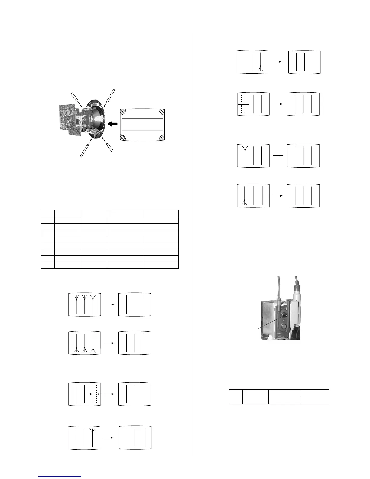
2-4. FOCUS ADJUSTMENT
1. Input monoscope signal.
2. Set video mode to STANDARD.
3. Adjust focus VR counter-clockwise to confi rm that the dot’s shape is
centered.
4. Confi rm center focus with focus VR.
FOCUS
2-5. SCREEN (G2)
1. Input a monoscope pattern (NTSC)
2. Set to service mode and adjust as follows:
CXA 2150P-2
NO. Disp. Item Avg.
0 ALBK ALL_BLK 0
3. Adjust RV9002 on the C Board so that the voltage on red, green and
blue cathodes is 170.0 0.5 V DC.
4. Adjust the hotizontal line at the top of the screen so it is cut off.
Note: Never set ALBK to 1 when external power supply is connected
to cathode.
 Loading...