— 6 —
KV-32HS20/36HS20/36HS20H/32XBR450/36XBR450/36XBR450H
SELF-DIAGNOSTIC FUNCTION
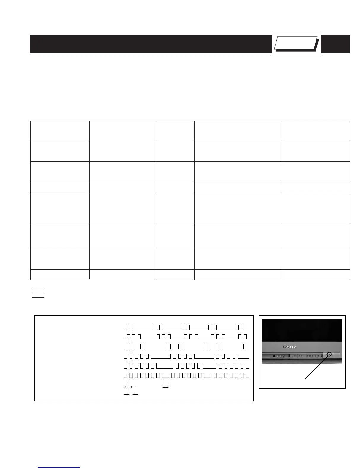
Display of Standby/Timer LED Flash Count
Diagnostic items Flash count
Lamp OFF 3 sec.
Lamp ON 0.3 sec.
Lamp OFF 0.3 sec.
Standby/Timer LED
+B overcurrent 2 times
+B/Low B overvoltage 3 times
Vert. deflection stopped 4 times
White balance failure 5 times
Low B error 6 times
Horiz. deflection stopped 7 times
Stopping the Standby/Timer LED Flash
Turn off the power switch on the TV main unit or unplug the power cord from the outlet to stop the STANDBY/TIMER LAMP from fl ashing.
Self-Diagnostic Screen Display
For errors with symptoms such as “power sometimes shuts off” or “screen sometimes goes out” that cannot be confi rmed, it is possible to bring up
past occurrences of failure on the screen for confi rmation.
The units in this manual contain a self-diagnostic function. If an error occurs, the STANDBY/STEREO LED will automatically begin to fl ash. The number
of times the LED fl ashes translates to a probable source of the problem. A defi nition of the STANDBY/STEREO LED fl ash indicators is listed in the
instruction manual for the user’s knowledge and reference. If an error symptom cannot be reproduced, the Remote Commander can be used to review
the failure occurrence data stored in memory to reveal past problems and how often these problems occur.
Diagnostic Test Indicators
When an error occurs, the STANDBY/STEREO LED will fl ash a set number of times to indicate the possible cause of the problem. If there is more
than one error, the LED will identify the fi rst of the problem areas.
Results for all of the following diagnostic items are displayed on screen. If the screen displays a “0”, and error has occurred.
No. of times STANDBY/
Diagnostic Item STEREO lamp fl ashes Display Result Probable Cause Location Detected Symptoms
Power does not turn on Does not light • Power cord is not plugged in. • Power does not come on.
• Fuse is burned out (F5501) • No power is supplied to the TV.
• AC power supply is faulty.
+B overcurrent (OCP) 2 times 2:0 or 2:1 • H.OUT (Q5030) is shorted. (D Board) • Power does not come on.
(see Note 1) • +B PWM (Q5003) is shorted (D Board) • Load on power line is shorted.
• IC9001, IC9002, IC9003 is shorted (C Board)
Low B overvoltage (OVP) 3 times 3:0 or 3:1 • IC6505 is faulty. (D Board) • Has entered standby mode.
Vertical defl ection stopped 4 times 4:0 or 4:1 • ± 15V is not supplied. (D Board) • Has entered standby state after
• IC5004 is faulty. (D Board) horizontal raster.
• Vertical defl ection pulse is stopped.
• Power line is shorted or power
supply is stopped.
White balance failure 5 times 5:0 or 5:1 • Video OUT (IC9001-IC9003) is faulty. • No raster is generated.
(not balanced) (C Board) • CRT cathode current detection
• CRT drive (IC201) is faulty. (A Board) reference pulse output is small.
• G2 is improperly adjusted. (see Note 2)
LOW B OCP/OVP 6 times 6:0 or 6:1 • +5 line is overloaded. (A, B Boards) • No picture
(overcurrent/overvoltage) • +5 line is shorted. (A, B Boards)
(see Note 3) • IC6007 is faulty. (A Board)
Horizontal Defl ection stopped 7 times 7:0 or 7:1 • No picture
Note 1: If a +B overcurrent is detected, stoppage of the vertical defl ection is detected simultaneously. The symptom that is diagnosed fi rst by the microcontroller is displayed on screen.
Note 2: Refer to Screen (G2) Adjustment in Section 3-4 of this manual.
Note 3: If STANDBY/STEREO LED fl ashes six (6) times, unplug the unit and wait 10 seconds before performing the adjustment
Self Diagnosis
Supported model
* One fl ash count is not used for self-
diagnostic.
 Loading...