CPD-1302
CPD-1302
SECTION 3
NOTE:
SAFETY RELATED ADJUSTMENT
(1)
TEST EQUIPMENT REQUIRED
1.
Yoltmeter (YOM)
2. Digital multimeter
3.
DC
POWER SUPPLY.
4.
SONY Microcomputer
SMC-70
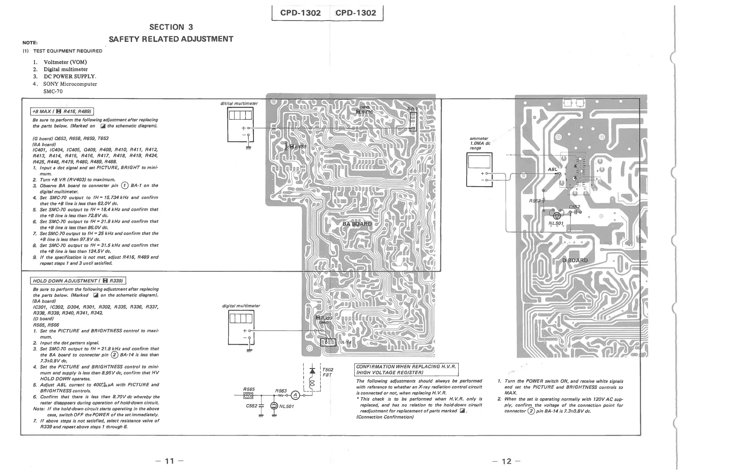
I +B
MAx
( 8 R416, R489) I
Be
sure
to
perform
the
following
adiustment
after
replacing
the parts below. (Marked on
~
the schematic diagram).
(G board)
0653,
R658, R659, T653
(BA board)
IC401, IC404, IC405,
0409,
R409, R410,
R4",
R412,
R413, R414, R415, R416, R417, R418, R419, R424,
R425, R448, R479, R480, R489,
R488.
1.
Input
a
dot
signal
and
set PICTURE,
BRIGHT
to
mini-
mum.
2.
Turn +B VR
(RV403)
to
maximum.
3.
Observe BA board
to
connecter
pin
CD
BA-1
on
the
digital
multimeter.
4.
Set SMC-70
output
to
fH
= 15.734
kHz
and
confirm
that
the +B line
is
less
than
62.0V
dc.
5.
Set SMC-70
output
to
fH
= 18.4
kHz
and
confirm
that
the +B line
is
less
than
728V
dc.
6.
Set SMC-70
output
to
fH
-
21.8
kHz
and
confirm
that
the +B line
is
less
than
86.0V
dc.
7.
Set SMC-70
output
to
fH
'"
25
kHz
and
confirm
that
the
+B line is
less
than
97.8
V
dc.
B.
Set SMC-70
output
to
fH
=
31.5
kHz
and
confirm
that
the +B line is
less
than
124.5V
dc_
9.
If
the specification is
not
met, adiust R416,
R489
and
repeat steps 1
and
3
until
satisfied.
I HOLO DOWN
ADJUSTMENT
( B R339) I
Be
sure
to
perform
the
following
adiustment
after
replacing
the parts below. (Marked
~
on
the schematic diagram).
(BA board)
IC301, IC302, D304, R301, R302, R335, R336, R337,
R338, R339, R340, R341,
R342.
(D board)
R565,
R566
1.
Set the
PICTURE
and
BRIGHTNESS
control
to maxi-
mum.
2·
Input
the
dot
pattern signal.
3_
Set SMC-70
output
to
fH
=
21.8
kHz
and
confirm
that
the
BA
board
to connecter
pin
0
BA-14
is
less
than
7.3±0.8V
dc_
4.
Set the
PICTURE
and
BRIGHTNESS
control
to
mini-
mum
and
supply
is
less
than
8.95
V dc,
confirm
that
HV
HOLD
DOWN
operates.
5.
Adiust
ABL
current
to
400~fojJA
with
PICTURE
and
BRIGHTNESS
controls.
6.
Confirm
that
there
is
less
than
8.70
V dc whereby the
raster disappears during operation
of
hold-down
circuit
Note:
If
the
hold·down
circuit
starts operating in the above
case,
switch
OFF
the POWER
of
the set immediately.
7.
If
above steps
is
not
satisfied, select resistance valve
of
R339
and
repeat above steps 1 through
6.
-
11
-
digital
multimeter
ammeter
1.0MA dc
III
Ii
}o-:-J
--~e.N
~~~~~~
I
: T502
I
FBT
I
CONFIRMATION
WHEN
REPLACING
H.
V.R.
(HIGH
VOL
TAGE
REGISTER)
The
following
adiustments should always be
performed
with reference to whether an-X-ray radiation
control
circuit
is
connected
or
not, when replacing
H.
V.
R.
• This check
is
to
be
performed
when
H.
V.R.
only
is
replaced,
and
has
no
relation to the hold-down
circuit
readiustment
for
replacement
of
parts marked
~.
(Connection Confirmation)
1.
Turn the POWER switch ON,
and
receive white signals
and set the
PICTURE
and
BRIGHTNESS controls
to
MAX.
2
When
the set
is
operating
normally
with
120V
AC
sup-
ply,
confirm
the voltage
of
the connection
point
for
connector 0
pin
BA-14
is
7.
3±0. 8 V
dc.
-
12-