)
3-3 ADJUSTMENT
OF
HORIZONTAL DELAY
SYNC
PULSE
1.
Signal
H:
15.734 kHz
V:
60
Hz
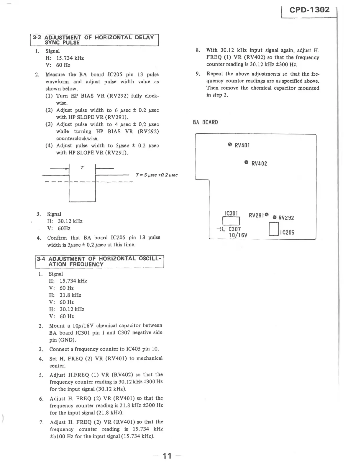
2.
Measure the BA board IC20S pin
13
pulse
waveform and adjust pulse width value as
shown below.
(1)
Turn
HP
BIAS VR
(RV292)
fully clock-
wise.
(2) Adjust pulse
width
to
6 Jlsec ± 0.2 Jlsec
with
HP SLOPE VR (RV291).
(3) Adjust pulse width
to
4 Jlsec ± 0.2 Jlsec
while turning HP BIAS VR (RV292)
counterclockwise.
(4) Adjust pulse width
to
SJlsec ± 0.2 Jlsec
with
HP
SLOPE VR
(RV29l).
T
3. Signal
H: 30.12 kHz
V:
60Hz
T""
5 jl.SeC ±O.2
fJ.SI1C
4. Confirm
that
BA
board IC20S pin 13 pulse
width
is 3Jlsec ± 0.2 Jlsec at this time.
3-4 ADJUSTMENT
OF
HORIZONTAL OSCILL-
ATION
FREQUENCY
1.
Signal
H: 15.734 kHz
V: 60 Hz
H:
21.8 kHz
V:
60
Hz
H: 30.12 kHz
V: 60
Hz
2. Mount a 10Jl/16V chemical capacitor between
BA board
IC30 1 pin 1 and C307 negative side
pin (GND).
3. Connect a frequency
counter
to
IC40S pin 10.
4. Set
H.
FREQ (2) VR
(RV40l)
to
mechanical
center.
5.
Adjust H.FREQ
(1)
VR
(RV402)
so
that
the
frequency
counter
reading is 30.12 kHz ±300 Hz
for
the
input
signal (30.12 kHz).
6. Adjust
H.
FREQ (2) VR (RV401)
so
that
the
frequency counter reading is 21.8 kHz
±300 Hz
for
the
input
signal (21.8 kHz).
7. Adjust
H.
FREQ (2) VR
(RV40l)
so
that
the
frequency
counter
reading is 15.734 kHz
±blOO
Hz
for
the
input
signal
(15.734
kHz).
-
11
-
CPD-1302
8. With 30.12 kHz
input
signal again, adjust
H.
FREQ
(1)
VR
(RV402) so that the frequency
counter reading
is 30.12 kHz ±300 Hz.
9. Repeat
the
above adjustments
so
that
the fre-
quency counter readings are
as
specified above.
Then remove
the
chemical capacitor
mounted
in step 2.
BA
BOARD
o
RV401
o
RV402
IC30t
o
~I:t
C307
10/16V
RV291
0
0
RV292
D'C205