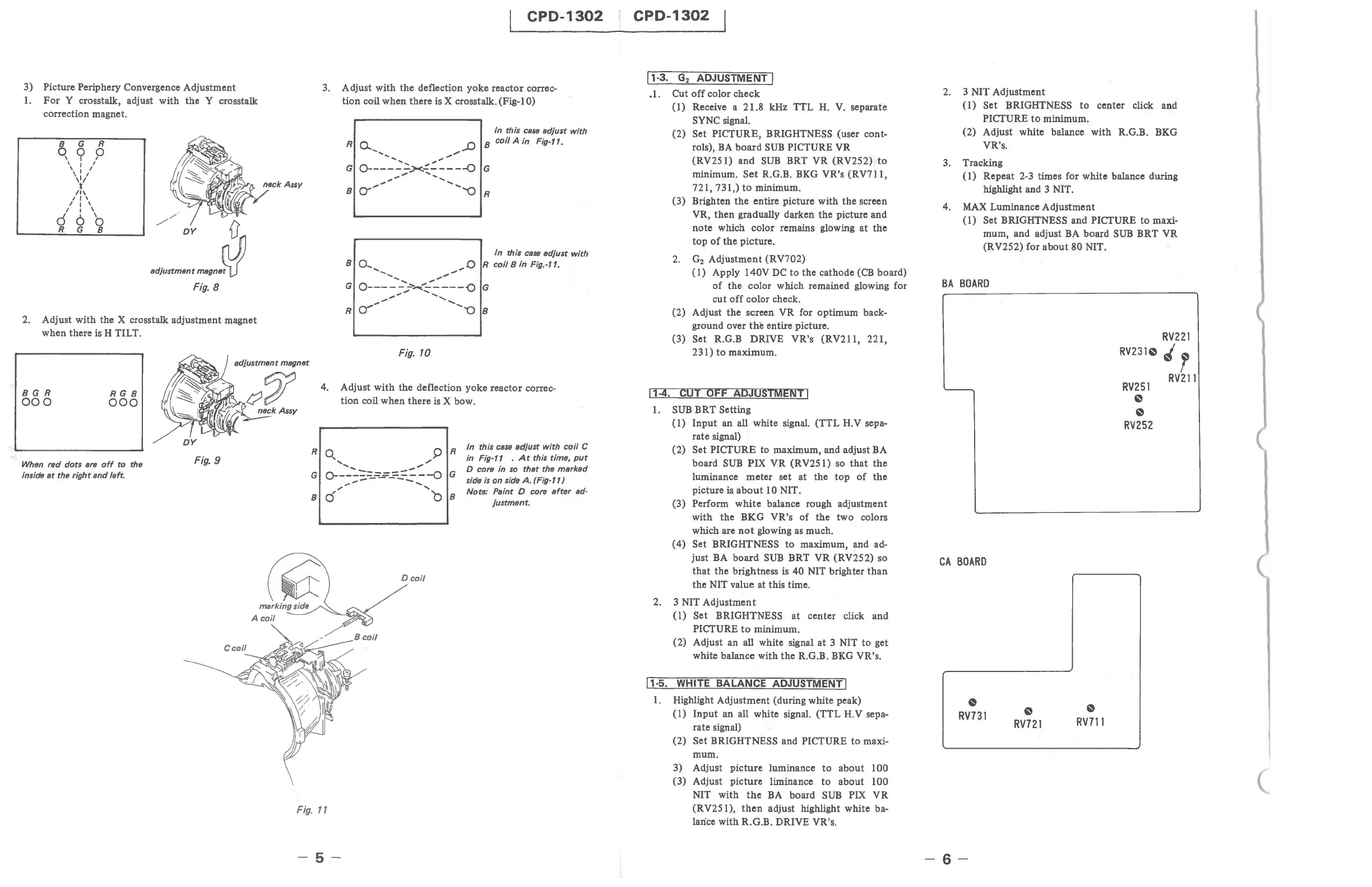
3) Picture Periphery Convergence Adjustment
1.
For
Y crosstalk, adjust with
the
Y crosstalk
correction magnet.
8 G R
q « p
, I I
, I I
\ I I
't'
/1\
I I ,
/ I ,
/ I ,
d 6
'0
R G 8
//
h
DY
1),
•
d}u"",,"'
......
PJ!
Fig.
8
2. Adjust with the X crosstalk adjustment magnet
when there
is H TILT.
CPD-1302
3.
Adjust with the deflection yoke reactor correc-
tion
coil when there is X crosstalk. (Fig-I 0)
In
this case adjust with
8 coil A in
Fig-ft.
In
this cass adjust with
8 0.... ",,0 R coil 8 in Fig.-ft.
....
...
..........
..".."""
G
O-----:~~----{)
G
.."
,,"
.............
""
...........
R~
"08
Fig. 10
adjustment magnet
BGR
000
RG8
000
When red dots
are
off
to
the
inside
at
the
rightsnd
left.
DY
Fig. 9
4. Adjust
with
the deflection yoke reactor correc-
tion coil when there
is
X bow.
Fig.
11
-5-
R
In
this case adjust with coil C
in
Fig-l1 .
At
this time,
put
D core in so that the marked
G side
is
on side
A.
(Fig-l1)
Note: Paint D core after ad-
8
justment.
CPD-1302
11-3.
G
2
ADJUSTMENT 1
_I.
Cut
off
color check
(1)
Receive a 21.8 kHz TTL
H.
V.
separate
SYNC signal.
(2)
Set PICTURE, BRIGHTNESS (user cont-
rols),
BA
board
SUB
PICTURE VR
(RV251) and
SUB
BRT VR (RV252)
to
minimum.
Set
R.G.B. BKG VR's (RV711,
721,731,)
to
minimum.
(3) Brighten
the
entire picture with the screen
VR, then gradually darken the picture and
note which color remains glowing at
the
top
of
the
picture .
2.
G
2
Adjustment (RV702)
(1)
Apply 140V
DC
to
the cathode
(CB
board)
of
the color which remained glowing for
cut
off
color check.
(2) Adjust
the
screen VR for optimum back-
ground over
the
entire picture.
(3) Set R.G.B DRIVE VR's (RV211, 221,
231)
to
maximum.
11-4.
CUT OFF ADJUSTMENT 1
1.
SUB
BRT Setting
(1)
Input
an all white signal. (TTL H.V sepa-
rate signal)
(2)
Set PICTURE to maximum, and adjust BA
board
SUB
PIX VR (RV25
I)
so
that
the
luminance
meter
set at the
top
of
the
picture is
about
10 NIT.
(3)
Perform
white
balance rough adjustment
with the BKG VR's
of
the two colors
which are
not
glowing as much.
(4)
Set BRIGHTNESS
to
maximum, and ad-
just
BA
board
SUB
BRT VR (RV252) so
that
the brightness is 40 NIT brighter
than
the NIT value at this time.
2. 3 NIT Adjustment
(1)
Set BRIGHTNESS at center click and
PICTURE
to
minimum.
(2) Adjust an
all white signal
at
3 NIT
to
get
white balance with
the
RG.B.
BKG
VR's.
11-5.
WHITE BALANCE ADJUSTMENT 1
1.
Highlight Adjustment (during white peak)
(1)
Input
an all white signal. (TTL H.V sepa-
rate signal)
(2)
Set BRIGHTNESS and PICTURE
to
maxi-
mum.
3) Adjust picture luminance
to
about 100
(3) Adjust picture liminance
to
about 100
NIT with
the
BA
board
SUB
PIX VR
(RV251),
then
adjust highlight white ba-
lance
with R.G.B. DRIVE VR's.
2.
3 NIT Adjustment
(1)
Set BRIGHTNESS
to
center click and
PICTURE
to
minimum.
(2) Adjust white balance with R.G.B. BKG
VR's.
3. Tracking
(I)
Repeat 2-3 times for white balance during
highlight and 3 NIT.
4.
MAX
Luminance Adjustment
(1)
Set BRIGHTNESS and PICTURE
to
maxi-
mum, and adjust
BA
board
SUB
BRT VR
(RV252) for
about
80 NIT.
BA
BOARD
CA
BOARD
~
RV731
-6-
~
RV721
~
RV711
RV231~
RV251
~
~
RV252
RV221
'r
RV211
(