SECTION 1
SETUP ADJUSTMENTS
11-1.
LANDING ADJUSTMENT 1
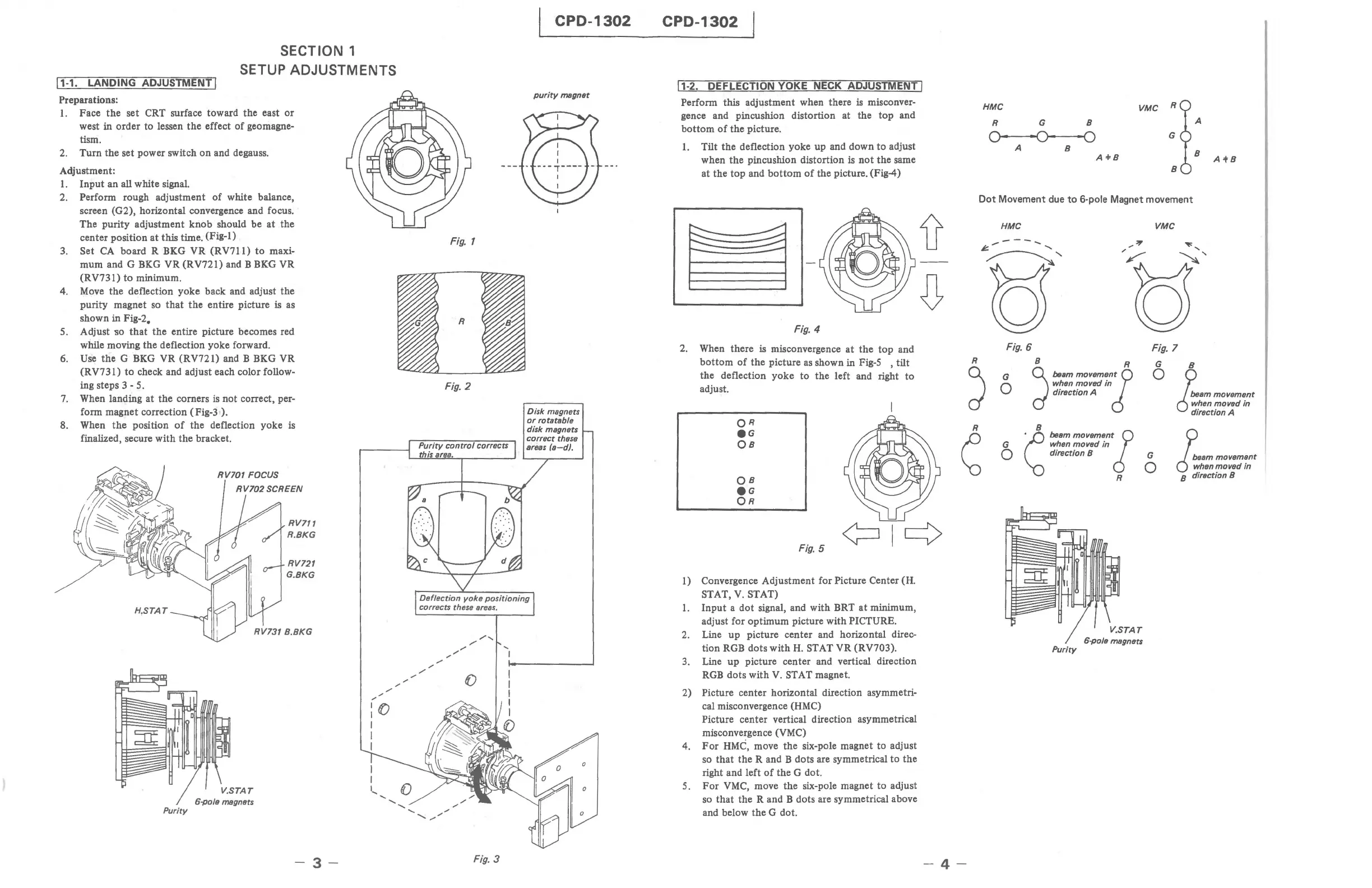
Preparations:
1.
Face
the
set CRT surface toward the east
or
west in order to lessen
the
effect
of
geomagne-
tism.
2.
Turn
the set power switch
on
and degauss.
Adjustment:
1.
Input
an all white signal.
2.
Perform rough adjustment
of
white balance,
screen (G2), horizontal convergence and focus.
The
purity
adjustment
knob
should be
at
the
center position
at
this time. (Fig-I)
3.
Set
CA
board R BKG VR
(RV71l)
to
maxi-
mum and G BKG VR (R V721) and B
BK-G
VR
(RV731)
to
minimum.
4.
Move
the
deflection yoke back and adjust the
purity magnet
so
that
the
entire picture is as
shown in Fig-2.
5. Adjust
110
that
the
entire picture becomes red
while moving the deflection yoke forward.
6.
Use
the
G BKG VR (RV72
I)
and B BKG VR
(RV731)
to
check and adjust each color follow-
ing steps 3 - 5.
7.
When landing at
the
corners
is
not
correct, per-
form magnet correction (Fig-3 I).
8. When
the
position
of
the deflection yoke
is
finalized, secure with
the
bracket.
Purity
V.STAT
6-po/e megnets
RV711
R.BKG
RV721
G.BKG
-3-
,;
'"
Fig.
1
Fig. 2
Purity control corrects
isar .
,/
,;
,/
..,,,"'"
0
,/
:0
I
I
I
I
I
I
....
()
.....
......
......
......
,;
.......
",;
Fig. 3
CPD-1302
purity megnet
o
o
CPD-1302
11-2.
DEFLECTION YOKE NECK ADJUSTMENT I
Perform this adjustment when there
is
misconver-
gence and pincushion distortion at the
top
and
bottom
of
the
picture.
1.
Tilt the deflection yoke up and down
to
adjust
when
the
pincushion distortion
is
not
the
same
at the
top
and
bottom
of
the picture. (Fig-4)
Fig. 4
2. When there
is
misconvergence
at
the
top and
bottom
of
the picture
as
shown in
Fig-S
,tilt
the deflection yoke
to
the
left and right
to
adjust.
Fig.
5
1) Convergence Adjustment for Picture Center (H.
STAT,
V.
STAT)
1.
Input
a dot signal, and with BRT
at
minimum,
adjust for optimum picture with
PICTURE.
2.
Line up picture center and horizontal direc-
tion RGB dots
with
H.
STAT VR (RV703).
3.
Line
up
picture center and vertical direction
RGB
dots with V. STAT magnet.
2)
Picture center horizontal direction asymmetri-
cal misconvergence (HMC)
Picture center vertical direction asymmetrical
misconvergence (VMC)
4.
For
HMC,
move the six-pole magnet to adjust
so
that
the
Rand
B dots are symmetrical
to
the
right and left
of
the
G dot.
5.
For
VMC,
move
the
six-pole magnet
to
adjust
so
that
the
Rand
B dots are symmetrical above
and below
the
G dot.
-4-
HMC
VMC
R
R
G B
A
O·
-0-
"0
G
A
B
B
A+B
A'tB
B
Dot Movement due
to
6·pole Magnet movement
HMC
VMC
6;",..---
.............
~'
Fig.
6
Fig. 7
R
J
G
o
d
B beam
movemenlR
when moved
in
direction A
G B
o
~am
movement
d
;hen
moved
in
direction A
G
~B
~::,:
:~~:;~~tl
o direction B G
o
R
6-po/e megnets
Purity
~em
movement
d
~hen
moved
in
B direction B