,
VCC
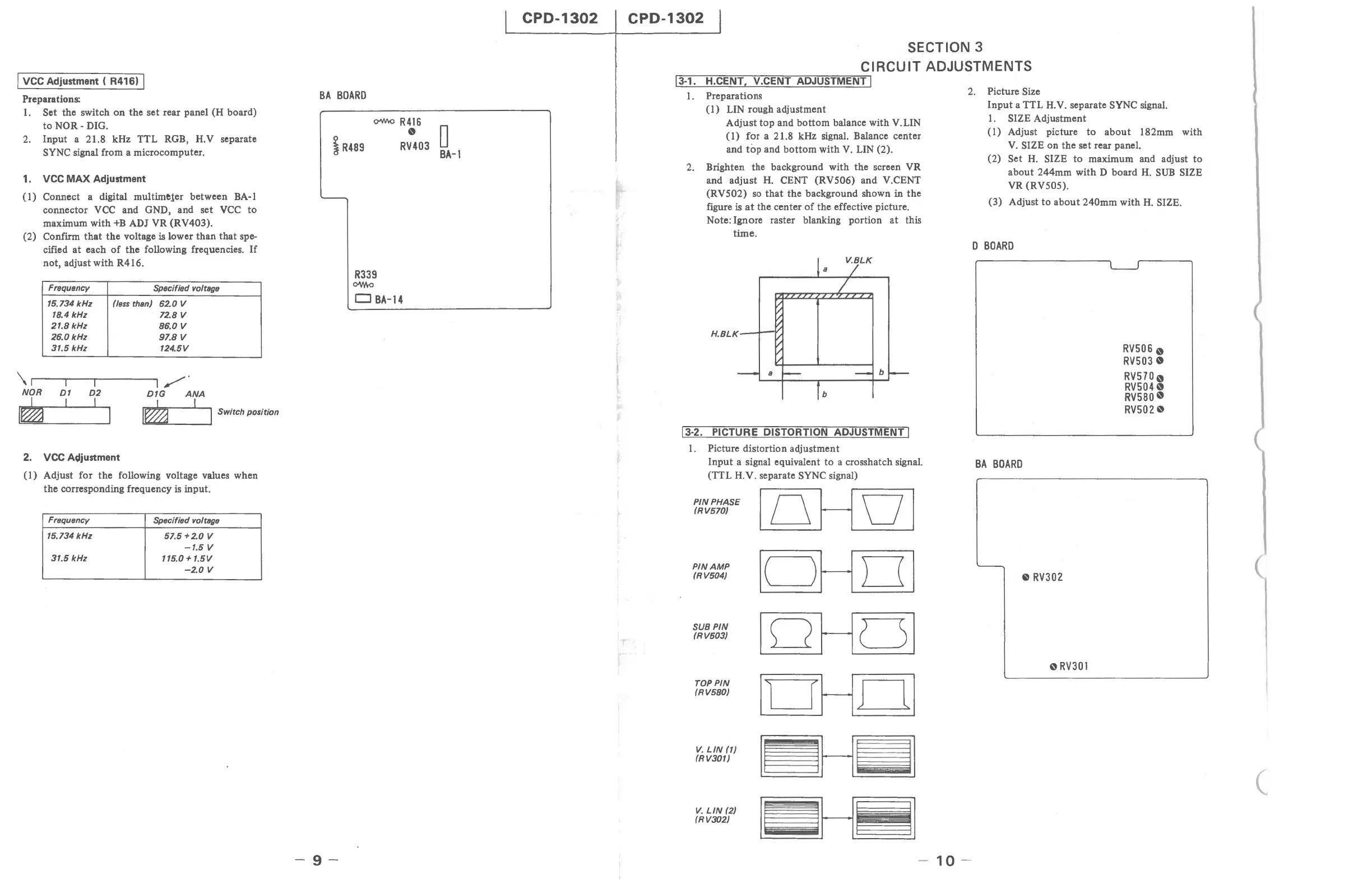
Adjustment ( R416) I
Preparations:
1.
Set the switch
on
the set rear panel (H board)
to
NOR-
DIG.
2.
Input a 21.8 kHz TTL RGB, H.V separate
SYNC signal from a microcomputer.
1.
VCC
MAX
Adjustment
(1)
Connect a digital muitime,ter between BA-l
connector
VCC
and GND, and set
VCC
to
maximum with
+B
ADJ VR (RV403).
(2) Confirm
that
the
voltage
is
lower than
that
spe-
cified
at
each
of
the following frequencies.
If
not, adjust with R416.
Frequency
Specified voltage
15.734
kHz
(less
than) 62.0 V
18.4
kHz
72.8 V
21.8
kHz
86.0
V
26.0
kHz
97.8
V
31.5 kHz 124.5V
\1
r
---rl
-'"TI---~I
/"'"
NOR
01
D2
D1G
ANA
I
L 1 I
,=
I
~
.~
J Switch position
2.
VCC
Adjustment
(1)
Adjust for the following voltage values when
the corresponding frequency
is
input.
Frequency
Specified voltage
15.734
kHz
57.5+2.0
V
-1.5
V
31.5
kHz
115.0 +
1.5V
-2.0
V
BA
BOARD
i
R489
C>"/'hO
R 4
16
R~03
0
BA-l
-9-
R339
ow.a
CJ
BA-14
CPD-1302
CPD-1302
SECTION 3
CIRCUIT ADJUSTMENTS
1'l13
Li
-11.
----UH7.C'i:E;";N
IT
T'---,
'-V".C"'E""NT-;T;:---'-A-;:;;D:-;;JU"""S=T=M=E=N"";T::'I
1.
Preparations
(1) LIN rough adjustment
Adjust
top
and
bottom
balance with V.LIN
(1) for a 21.8 kHz signal. Balance center
and
top
and
bottom
with
V.
LIN (2).
2.
Brighten the background with the screen VR
and adjust
H.
CENT (RV506) and V.CENT
(RV502)
so
that
the background shown in
the
figure
is
at
the center
of
the effective picture.
Note: Ignore raster blanking portion
at
this
time.
13-2.
PICTURE DISTORTION ADJUSTMENT I
1.
Picture distortion adjustment
Input
a signal equivalent
to
a crosshatch signal.
(TTL
H.Y. separate SYNC signal)
PIN
PHASE
loHOI
(RV570)
PIN
AMP
Ic=JHOI
(RV504)
loHCSI
SUB
PIN
(RV503)
TOPPIN
Il~HCLI
(RV580)
V.
LIN
(1)
I~HiiJl
(RV301)
I~H~I
V.
LIN
(2)
(RV302)
2.
Picture Size
10
-
Input
a TTL H.V. separate SYNC signal.
1.
SIZE Adjustment
(1)
Adjust picture
to
about
182mm with
V.
SIZE on the set rear panel.
(2)
Set H. SIZE
to
maximum and adjust
to
about 244mm with D board
H.
SUB
SIZE
VR (RV505).
(3) Adjust
to
about
240mm with
H.
SIZE.
D
BOARD
BA
BOARD
'--
e
RV302
oRV301
RV5060
RV5030
RV5700
RV5040
RV580
0
RV5020
(