Jote: The
components
identified by shading and mark
& are critical
for
safety. Replace only with
part
number
specified.
~ote:
Les composants identifi6s
par
une
trame
et
par
une
marque
&
sont
d'une
importance
:::
critique
pour
la
s6curit6.
Ne
les remplacer
Que
par
des pieces
de
num6ro sp6cifi6.
te:
All
capacitors ara
in
JJF
unless otherwisa noted. p :
JJJJF
50WV
or
less
are
not
indicated except for electrolytics.
All
resistors ara in ohms, 1/6W unlass otherwise noted. k :
1000n,
M :
1000kn.
m- : nonflammable rasitor.
All
variable and adjustable resistors have characteristic curve
B,
unless otherwise notad.
~:
fusible resitor.
A : internal component.
~
: panel designation.
lit : selected
to
yield
optimum
performance.
The components indantified by
B in this manual have been
carefully factory-selectee;! for aach
sat
in
order
to
satisfy re-
gulations regarding X-ray radiation. Should replacement be
required, replace
only with
the
value originally used.
When replacing components identified by
[;i
mark
the
neces-
sary adjustments indicated.
If
results
do
not
meet
the
specified
value, change the
component
identified by
IB
and repeat
the
adjustmant until
the
specified value
is
achieved.
(Refer
to
R339, R416, R489 adjustment
on
page 11,
12.1
When replacing
the
part
in
below table, be usre
to
perform
the
related adjustment.
Part replaced 1
~
) Adjustment 1 8 )
Board)
0653,
R658. R659.
T653
A Board)
401.
IC404. IC405,
0409.
R409. R410. R411,
R416. R489
J12, R413. R414, R415, R416, R417, R418,.
1+8
MAX)
119, R424, R425, R448, R479, R480, R488,
189.
A Board)
301,IC302,
R301, R302, R335, R336, R337, R339
A
B
c
D
E
F
G
138,
R339, R340, R341, R342,
0304
IHV
HOLD
DOWN)
Board) R565, R566
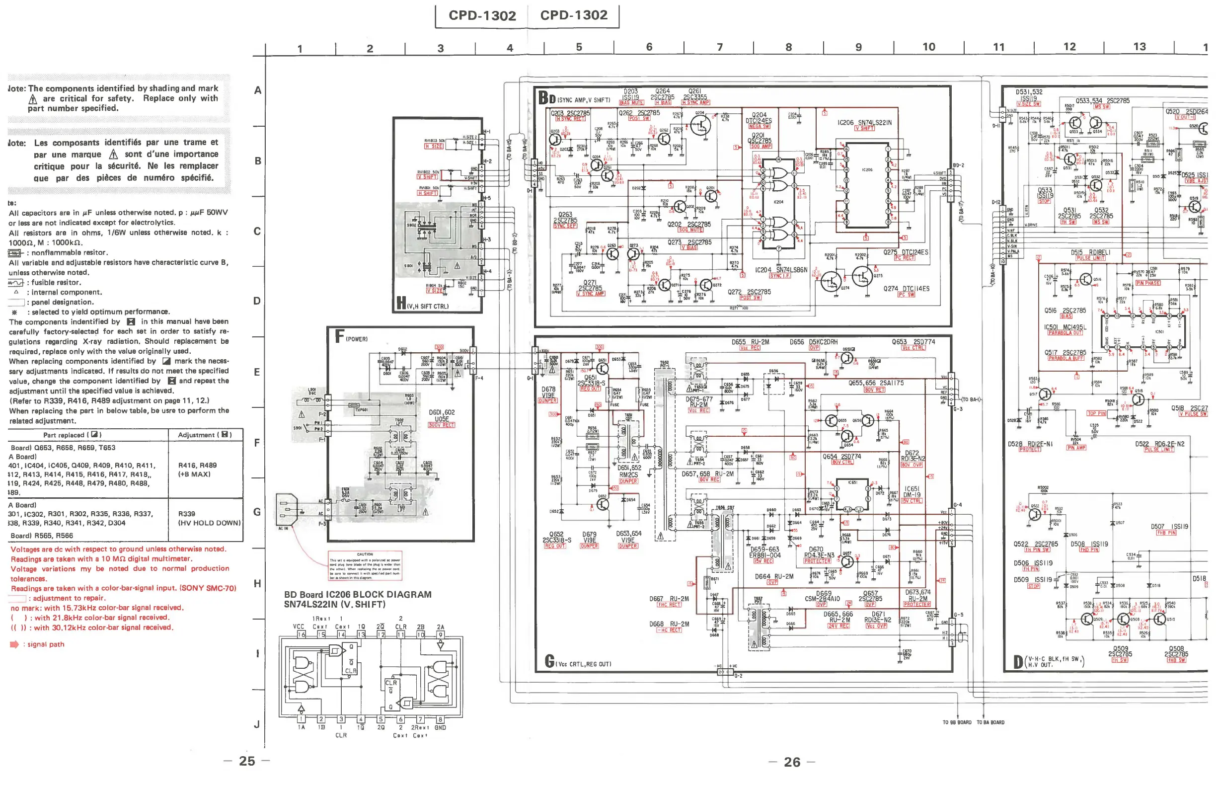
Voltages are dc with respect
to
ground unless otherwise noted.
Readings are taken with a
10
Mn
digital multimeter.
Voltage variations my
be noted due
to
normal production
tolerances.
Readings are taken with a color-bar-signal input. (SONY
SMC-701
----=:J
: adjustment
to
repair.
no mark: with 15.73kHz color-bar
signal received.
(
I:
with 21.8kHz color-bar signal received.
((
II
: with 3O.12kHz color-bar signal received.
• : signal path
H
J
25
CPD-1302
CPD-1302
1
2
3
N
.
~
'"
~-I
RV1
a03
~
~
~
L...l....-J
I
+--
~
.. ,
' W ' W
T
TlIHO'
SlOt
ow,
1"-1
~
.r
'102
r-'!l
.".
!tOWI
0601,602
U05E
~
.--
Me
~
I~
~~
I "
ac
~
.
!I..re
1!'J!\
L
__
=-
~
Ae
~
I
~
~
r~
&
~
I"-'''
~
-
''.
-
'''
-
_
-
;'::
-
:'
-
:'~
-
''''
-
';'''
-
K
-
_
-----''''''
~
_
..............
,,"
......
;
.....
,,""
the DIIII1'I When '
....
1CinI
the
Ie
_ cord
blJU
....
~il
..
'thSPK,f,.cIpar111U11'1
blfaw-nlnthildi
...
_
BD
Board IC206 BLOCK DIAGRAM
SN74LS221N
(V. SHIFT)
I R. x t I
v~
cg,t
~t
~
-l16~
-lIS!.
-l14,
--1131.
2
AjH{~JL
I
...
IB
III
2!l
2Rn
t
tlND
Caxt
Cax
t
CLR
4
5
G I
Vee
CRTL,REG
OUT!
6
0203
0264
0261
~
2
nEm
5
~
~
0667
RU-2M
I1EDilll
0668
RU-2M
GKJ!illJ
7
8
9
10
1C206
1
5
~
7
A1
522
1
N
v H
BD-2
..
"'"
0274
OTC
II
4E5
Ipc
swl
L
:
-r
P<ro
BA-I
}
G-3
G-4
y" ,
1
11
J
0531,532
"y
.•
"
~
,,.,
""
12
0533,534
25C2785
'ffl
'
'
~'
13
R
~
~
1
I~
-
~~
:n
J~JI
~
~~
mil
""'"
row
·
4H
m
C557
+ 0531
22
0
533
D-12
'"
"31
.~
D$3l rr""'\. '-2
I'
''.",
101
''''''1
0.
7"
1
10.
10
k
10.
I
10.1
".
053
1
0532
lrH~~
5
21
iW,;1
5
~I'f
y.
y.
IV
.
PAL
'is
<OIItV
E
0'"
D(
V'H'C
BLK.fH
SW,)
H.V
OUT.
""
'"
"""
0509
25C2785
Illl::lll
..
..
'0
'
05l!
L _
ZS
lli
~
0
50
7
155119
"HB
PINI
0518
[l
!
~
~========~~===========
l~
~~~~~~
T
TO
BB
BOARO
TO
BA
BOARD
-
26
-