CPD-130
2 1
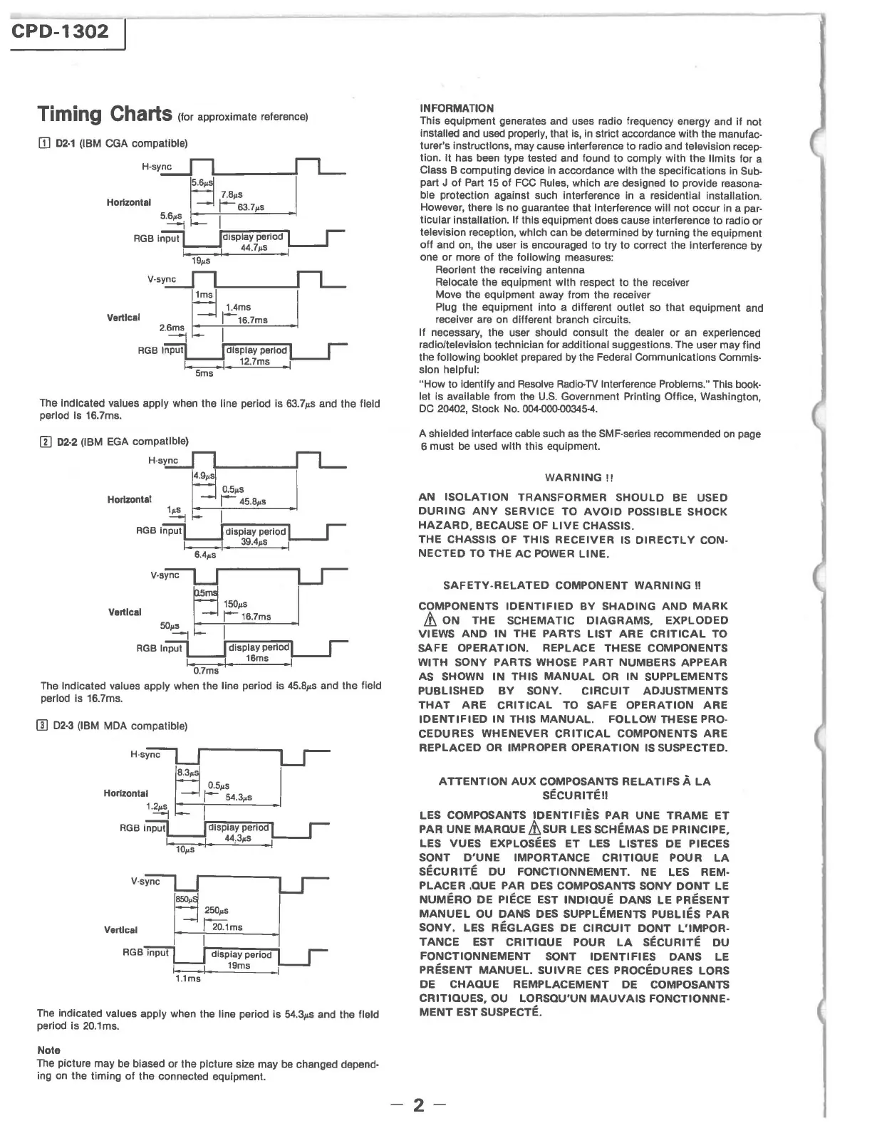
Timing Charts (for approximate reference)
[]
D2·1
(IBM
CGA
compatible)
The Indicated values apply when the line period
Is
63.7I's and the field
period
Is
16.7ms.
rn
D2·2
(IBM
EGA
compatible)
rn
02·3
(IBM
MOA
compatible)
H-sync
Horizontal
1.~
Vertical
250pS
I 20.1rns
display period
1--1.
19rns
Urns
The
indicated values apply when the line period Is
54.3JLS
and the field
period is
20.1
ms.
Note
The
picture may
be
biased or the picture size may
be
changed depend·
ing
on
the timing
of
the connected equipment.
INFORMATION
This equipment generates
and
uses radio frequency energy and
if
not
installed
and
used
properly, that
is,
in
strict accordance with the manufac·
turer's instructions, may cause interference to radio
and
television recep·
tion. It has
been
type tested
and
found to comply with the limits for a
Class B computing device
In
accordance with the specifications in
Sub-
part J
of
Part
15
of
FCC
Rules,
which
are
designed to provide reasona·
ble
protection against such interference
In
a residential installation.
However, there
Is
no guarantee that Interference will not occur in a par·
ticular installation. If
this equipment does cause interference to radio
or
television reception, which can
be
determined by turning the equipment
off and on, the user is encouraged to try to correct the interference by
one or more
of
the following measures:
Reorient the receiving antenna
Relocate the equipment with respect to the receiver
Move the equipment away from the receiver
Plug the equipment into a different outlet
so
that equipment and
receiver are on different branch circuits.
If necessary, the user should consult the dealer or an experienced
radloltelevlslon technician for additional suggestions.
The
user may find
the
following booklet prepared
by
the Federal Communications Commls·
slon helpful:
"How
to identify
and
Resolve
Radio-TV
Interference Problems." This book·
let
is available from the
U.S.
Government Printing Office, Washington,
DC
20402,
Stock
No.
0Q4.()()(J.()()345-4.
A shielded interface cable
such
as
the SMF·series recommended
on
page
6 must
be
used with this equipment.
WARNING
!!
AN
ISOLATION
TRANSFORMER
SHOULD
BE
USED
DURING
ANY
SERVICE TO
AVOID
POSSIBLE SHOCK
HAZARD,
BECAUSE OF
LIVE
CHASSIS_
THE CHASSIS OF THIS
RECEIVER
IS
DIRECTLY
CON·
NECTED
TO THE AC POWER LlNE_
SAFETY·RELATED
COMPONENT
WARNING
!!
COMPONENTS
IDENTIFIED
BY
SHADING
AND
MARK
&.
ON
THE
SCHEMATIC
DIAGRAMS.
EXPLODED
VIEWS
AND
IN
THE PARTS
LIST
ARE
CRITICAL
TO
SAFE OPERATION. REPLACE THESE COMPONENTS
WITH
SONY PARTS WHOSE
PART
NUMBERS APPEAR
AS SHOWN
IN
THIS
MANUAL
OR
IN
SUPPLEMENTS
PUBLISHED
BY
SONY.
CIRCUIT
ADJUSTMENTS
THAT
ARE
CRITICAL
TO
SAFE
OPERATION
ARE
IDENTIFIED
IN
THIS
MANUAL.
FOLLOW THESE PRO·
CEDURES
WHENEVER
CRITICAL
COMPONENTS
ARE
REPLACED
OR IMPROPER
OPERATION
IS SUSPECTED.
ATTENTION
AUX
COMPOSANTS
RELATIFS
A
LA
SECURITEII
LES COMPOSANTS
IDENTIFIES
PAR
UNE
TRAME
ET
PAR
UNE
MARQUE&'SUR
LESSCHEMAS
DE PRINCIPE,
LES
VUES
EXPLOSEES
ET
LES LISTES DE PIECES
SONT
D'UNE
IMPORTANCE
CRITIQUE
POUR
LA
SECURITE
DU
FONCTIONNEMENT.
NE LES REM·
PLACER
.QUE PAR DES COMPOSANTS SONY
DONT
LE
NUMERO
DE
PIECE EST
INDIQUE
DANS
LE
PRESENT
MANUEL
OU DANS DES SUPPLEMENTS
PUBLIES
PAR
SONY.
LES REGLAGES
DE
CIRCUIT
DONT
L'IMPOR·
TANCE
EST
CRITIQUE
POUR
LA
SECURITE
DU
FONCTIONNEMENT
SONT
IDENTIFIES
DANS
LE
PRESENT
MANUEL.
SUIVRE
CES PROCEDURES LORS
DE
CHAQUE
REMPLACEMENT
DE COMPOSANTS
CRITIQUES,
OU LORSQU'UN
MAUVAIS
FONCTIONNE·
MENT
EST SUSPECTE.
-2-