PVM-1353MD/1453MD
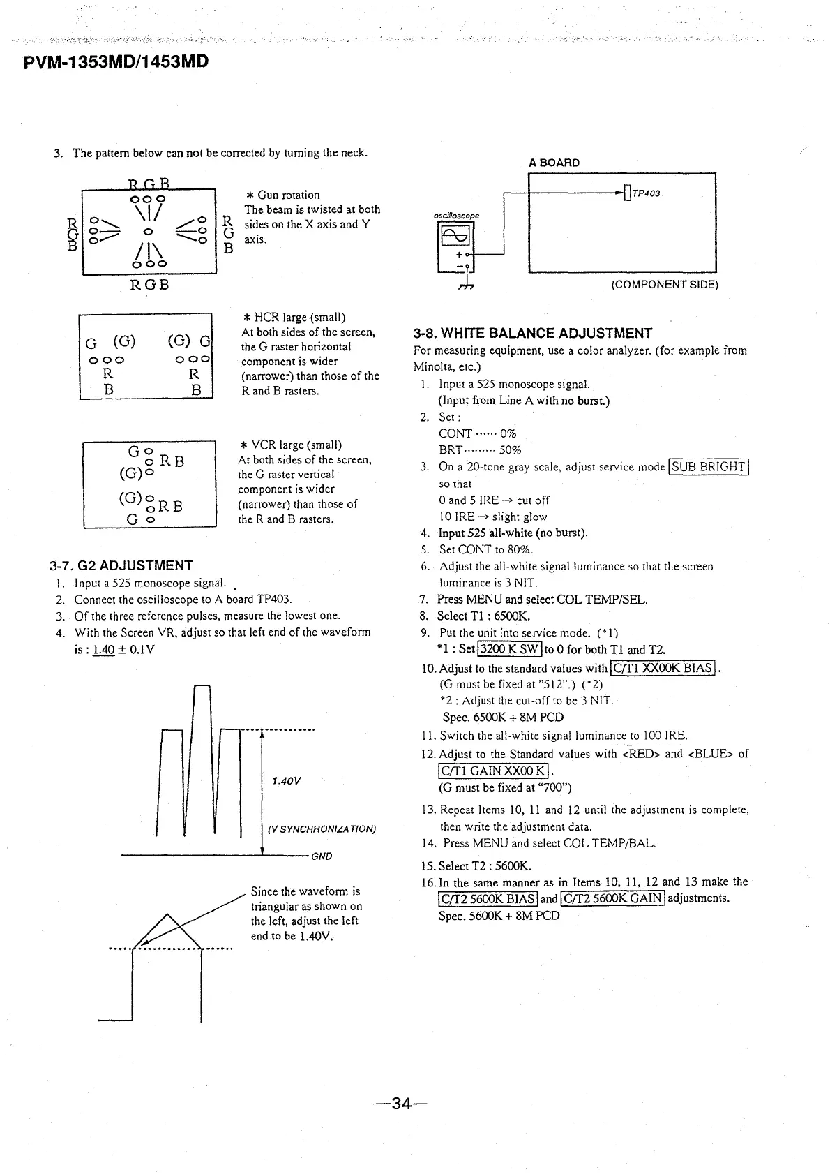
3. The pattern below can not be corrected by turning the neck.
~
000
\II
o......_,_
/0
o-
0
-0
0.,,.,,...
II\
--0
ooo
ROB
G (G)
(G) G
000
ooo
R
B
R
B
GoR
o B
(G)o
(G)«gRB
Go
3-7. G2 ADJUSTMENT
R
G
B
l. Input a 525 monoscope signal.
* Gun rotation
The beam is twisted at both
sides on the X axis and Y
axis.
* HCR large (small)
At both sides of the screen,
the G raster horizontal
component is wider
(narrower) than those of the
R and B rasters.
* VCR large (small)
At both sides of the screen,
the G raster vertical
component is wider
(narrower) than those of
the R and B rasters.
2. Connect the oscilloscope to A board TP403.
3. Of the three reference pulses, measure the lowest one.
4. With the Screen
YR, adjust so that left end of the waveform
is: 1.40
± O.lV
1.40V
(V SYNCHRONIZATION)
----------'----GND
Since the waveform is
triangular as shown on
the left, adjust the left
end to be 1.40V.
ABOARD
TP403
(COMPONENT SIDE)
3-8. WHITE BALANCE ADJUSTMENT
For measuring equipment, use a color analyzer. (for example from
Minolta, etc.)
I. Input a 525 monoscope signal.
(Input from Line A with no burst.)
2. Set:
CONT ...... 0%
BRT, ........ 50%
3. On a 20-tone gray scale, adjust service mode
I SUB BRIGHT j
so that
0 and 5
IRE_,. cut off
10
IRE_,. slight glow
4.
lriput 525 all-white (no burst).
5. Set CONT to 80%.
6. Adjust the all-white signal luminance so that the screen
luminance is 3 NIT.
7. Press MENU and select COL TEMP/SEL.
8. Select Tl : 6500K.
9. Put the unit into service mode.
(* 1)
* 1 : Set
I 3200 K SW l to O for both Tl and T2.
IO.Adjust to the standard values with
IC/Tl XXOOK BIAS!.
(G must be fixed at "512".)
(*2)
*2
: Adjust the cut-off to be 3 NIT.
Spec. 6500K
+ 8M PCD
11. Switch the all-white signal luminance to l 00 IRE.
12. Adjust to the Standard values with
<RED> and <BLUE> of
I C(fl GAIN xxoo K,.
(G must be fixed at "700")
I 3. Repeat Items 10, 11 and 12 until the adjustment is complete,
then write the adjustment data.
14. Press MENU and select COL TEMP/BAL.
15. Select T2 : 5600K.
16. In the same manner as in Items 10, 11, 12 and 13 make the
! crr2 5600K BIAS land! crr2 5600K GAIN l adjustments.
Spec. 5600K
+ 8M PCD
-34-