PVM-1353MD/1453MD
5. SMPTE SUB COLOR Adjustment
I. Input a component color bar (R-Y, Y, 8-Y). (SMPTE level
signal).
2. From the menu, make the Component Level N!O/SMPTE.
3. Connect the oscilloscope probe to IC404 Pin 30 or TP402.
4. Put the unit into service mode.
5. In the same manner as in 4-5, adjust
/SUB· CHROMA
N!O/SMPTE!.
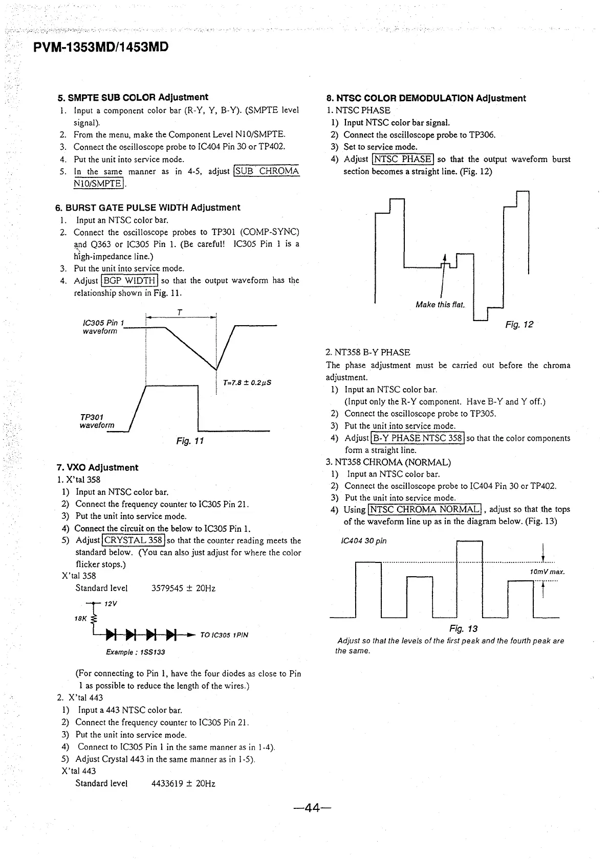
6. BURST GATE PULSE WIDTH Adjustment
I. Input an NTSC color bar.
2. Connect the oscilloscope probes to TP301 (COMP-SYNC)
f!nd Q363 or IC305 Pin 1. (Be careful! IC305 Pin l is a
hlgh-impedance line.)
3. Put the unit into service mode.
4. Adjust I BGP WIDTH
I so that the output waveform has the
relationship shown in Fig. l 1.
TP301J
w,,.ro,m
7. VXO Adjustment
1. X'tal 358
l) Input an NTSC color bar.
T
T=7.8 ± 0.2µ5
Fig. 11
2) Connect the frequency counter to IC305 Pin 21.
3) Put the unit into service mode.
4) Connect the circuit on the below to IC305 Pin I.
5) Adjust! CRYSTAL
358 j so that the counter reading meets the
standard below. (You can also just adjust for where the color
flicker stops.)
X'tal 358
Standard level
3579545
± 20Hz
1BK
T
12V
~
.. ,
~
~
~
TO/C3051PIN
Example: 1SS133
(For connecting to Pin I, have the four diodes as close to Pin
1 as possible to reduce the length of the wires.)
2. X'tal 443
I) Input a 443 NTSC color bar.
2) Connect the frequency counter to IC305 Pin 21.
3) Put the unit into service mode.
4) Connect to IC305 Pin I in the same manner as in l -4 ).
5) Adjust Crystal 443 in the same manner as in l -5).
X'tal 443
Standard level
4433619
± 20Hz
8. NTSC COLOR DEMODULATION Adjustment
I. NTSC PHASE
l) Input NTSC color bar signal.
2) Connect the oscilloscope probe to TP306.
3) Set to service mode.
4) Adjust
!NTSC PHASE! so that the output waveform burst
section becomes a straight line. (Fig. 12)
Make this flat.
Fig. 12
2. NT358 B-Y PHASE
The phase adjustment must be carried out before the chroma
adjustment.
1) Input an NTSC color bar.
(Input only the R-Y component. Have B-Y and Y off.)
2) Connect the oscilloscope probe to TP305.
3) Put the unit
into service mode.
4) Adjust
IB-Y PHASE NTSC 358 lso that the color components
form a straight line.
3. NT358 CHROMA (NORMAL)
I) Input an NTSC color bar.
2) Connect the oscilloscope probe to IC404 Pin 30 or TP402.
3) Put the unit into service mode.
4) Using
jNTSC CHROMA NORMAL!, adjust so that the tops
of the waveform line up as in the diagram below. (Fig. 13)
/C404 30pin
..................................................................... J .....
10mVmax.
Fig. 13
Adjust so that the levels of the first peak and the fourth peak are
the
same.
-44-