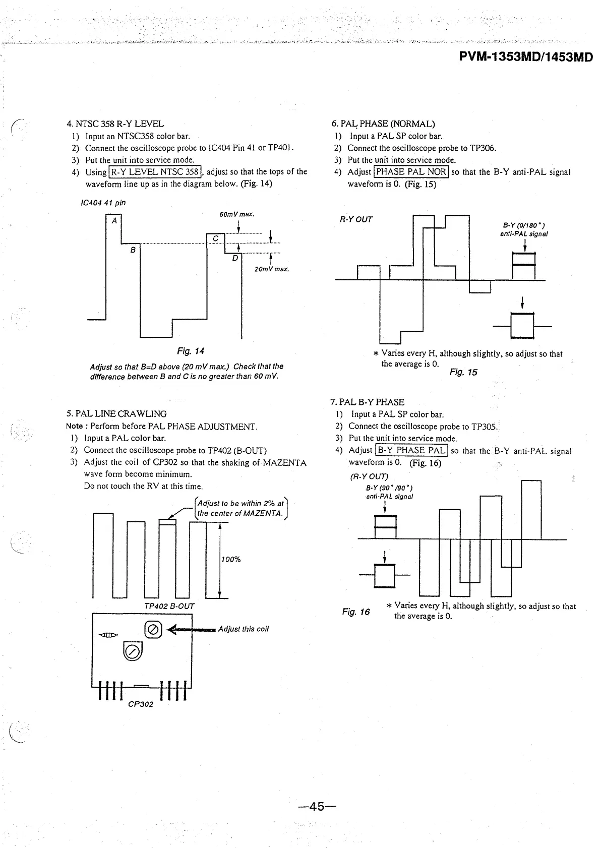
4. NTSC 358 R-Y LEVEL
I) Input an NTSC358 color bar.
2) Connect the oscilloscope probe to IC404 Pin 41 or TP401.
3) Put the unit into service mode.
4) Using
I R-Y LEVEL NTSC 358 j, adjust so that the tops of the
waveform line up as in the diagram below. (Fig. 14)
/C404 41 pin
60mVmax.
A
B
---···················· :; :::L
D ............. f .. ..
20mVmax.
Fig. 14
Adjust so that B=D above (20 mV max.) Check that the
difference between B and C is no greater than
60 m V.
5. PAL LINE CRA WUNG
Note: Perform before PAL PHASE ADJUSTMENT.
I) Input a PAL color bar.
2) Connect the oscilloscope probe to TP402 (B-OUT)
3) Adjust the coil of CP302 so that the shaking of MAZENTA
wave form become minimum.
Do not touch the RV at this time.
@)
(Adjust to be within 2% at)
~he
center of MAZENTA.
100%
TP4028-0UT
@) -4li-.--.. Adjust this coil
PVM-1353MD/1453MD
6. PA½ PHASE (NORMAL)
I) Input a PAL SP color bar.
2) Connect the oscilloscope probe to TP306.
3) Put the unit into service mode.
4) Adjust
I PHASE PAL NOR! so that the B-Y anti-PAL signal
wavefonn is 0. (Fig. 15)
R-YOUT
8-Y (0/180 °)
anti-PAL signal
F1
t
-0-
* Varies every H, although slightly, so adjust so that
the average is 0.
Fig. 15
7. PAL B-Y PHASE
I) Input a PAL SP color bar.
2) Connect the oscilloscope probe to TP305.
3) Put the unit into service mode.
4) Adjust
jB-Y PHASE PAL! so that the B-Y anti-PAL signal
waveform is 0. (Fig. 16)
(R-YOUT)
8-Y (90° /90°)
anti-PAL signal
t
t
-0-
Fig. 16
* Varies every H, although slightly, so adjust so that
the average is 0.
-45-