PVM-1353MD/1453MD
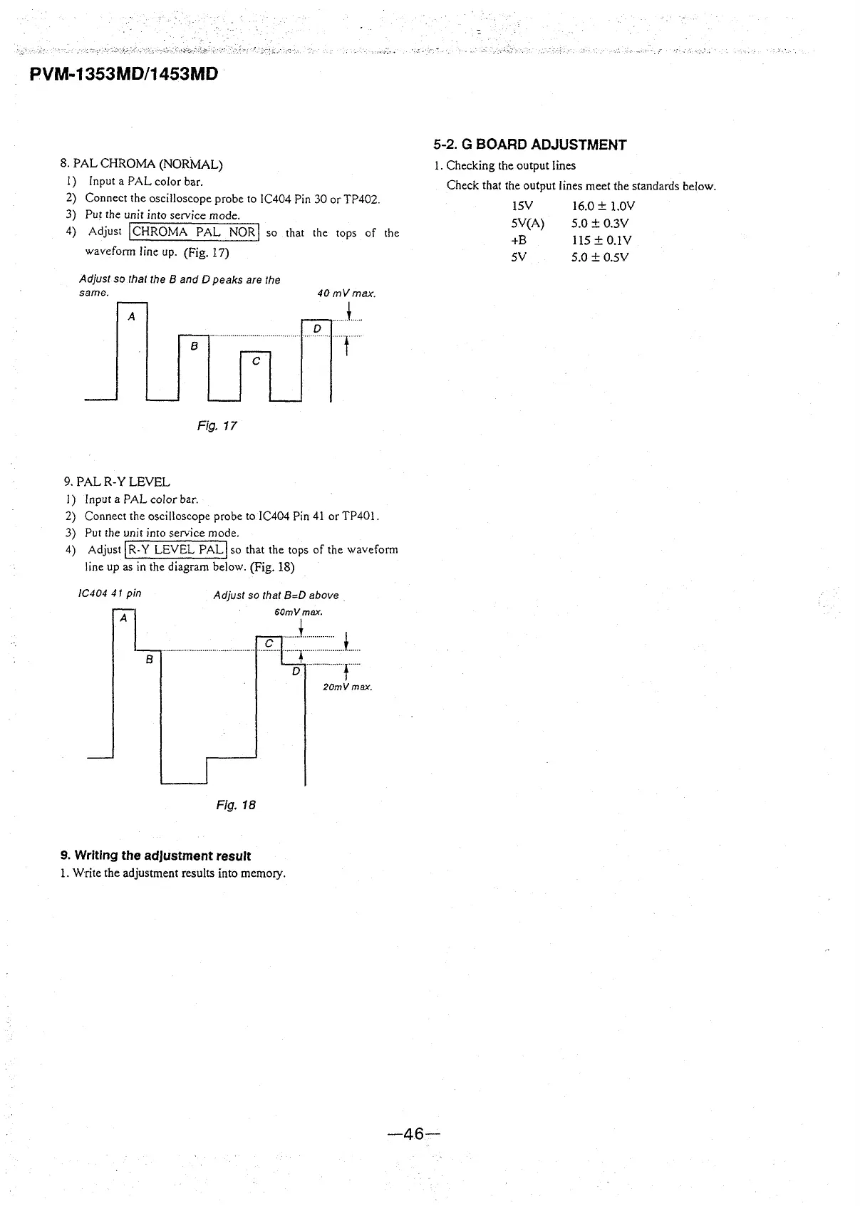
8. PAL CHROMA (NORMAL)
1) Input a PAL color bar.
2) Connect the oscilloscope probe to IC404 Pin 30 or TP402.
3) Put the unit into service mode.
4) Adjust
I CHROMA PAL NOR! so that the tops of the
waveform line up. (Fig. 17)
Adjust so that the B and D peaks are the
same.
A
a
C
Fig. 17
9. PALR-Y LEVEL
l) Input a PAL color bar.
40mVmax.
J ..
D
·····r··
2) Connect the oscilloscope probe to IC404 Pin 41 orTP401.
3) Put the unit into service mode.
4) Adjust
I R-Y LEVEL PAL! so that the tops of the waveform
line up as in the diagram below. (Fig. 18)
/C404 41 pin
B
Adjust so that B=D above
SOmVmax.
·······-··········· ················ ... c ... ::~ :=J ....
D ··················r··
20mVmax.
Fig. 18
9. Writing the adjustment result
l. Write the adjustment results into memory.
5-2. G BOARD ADJUSTMENT
l. Checking the output lines
Check that the output lines meet the standards below.
lSV 16.0 ± 1.0V
SV(A) 5.0 ± 0.3V
+B 115±0.IV
SY 5.0 ± 0.SV
-46-