18
(EN)
Note on the VPL-S900E model
The optional IFB-X600E Interface Board is required for the VIDEO IN
and AUDIO IN jacks.
Connecting
Connecting with a Computer
This section describes how to connect the projector with a computer.
For details on how to connect VCR or other equipment, see page 20 (EN).
When the projector is connected to a computer, you can control the mouse
of a computer by the Remote Commander.
The R/L CLICK keys and joy stick function as follows.
Note
Make sure that there is nothing to obstruct the infrared beam between the
Remote Commander and the remoter control detector on the projector.
Key and joy stick
IBM PC/AT
a)
Macintosh
compatible, Serial
R CLICK (front) Right button Mouse button
L CLICK (rear) Left button Mouse button
Joy stick Corresponds with the movements of the mouse
a) IBM PC/AT is a registered trademark of International Business Machines
Corporation, U.S.A.
Also refer to the instruction manual of equipment to be connected.
Notes
•This unit accepts the VGA, SVGA, XGA, and SXGA signals. However,
we recommend you to set the output mode of your computer to the
SVGA mode for the external monitor. (For Macintosh computer, set the
output mode to 16-inch mode.)
•If you set your computer, such as a notebook type IBM PC/AT
compatible, to output the signal to both the display of your computer and
the external monitor, the picture of the external monitor may not appear
properly. In such cases, set the output mode of your computer to output
the signal to only the external monitor.
For details, refer to the operating instructions supplied with your computer.
When making connections, be sure to:
•turn off all equipment before making any connections.
•use the proper cables for each connection.
•insert the plugs of the cables properly; plugs that are not fully inserted
often generate noise. When pulling out a cable, be sure to pull it out from
the plug, not the cable itself.
Function
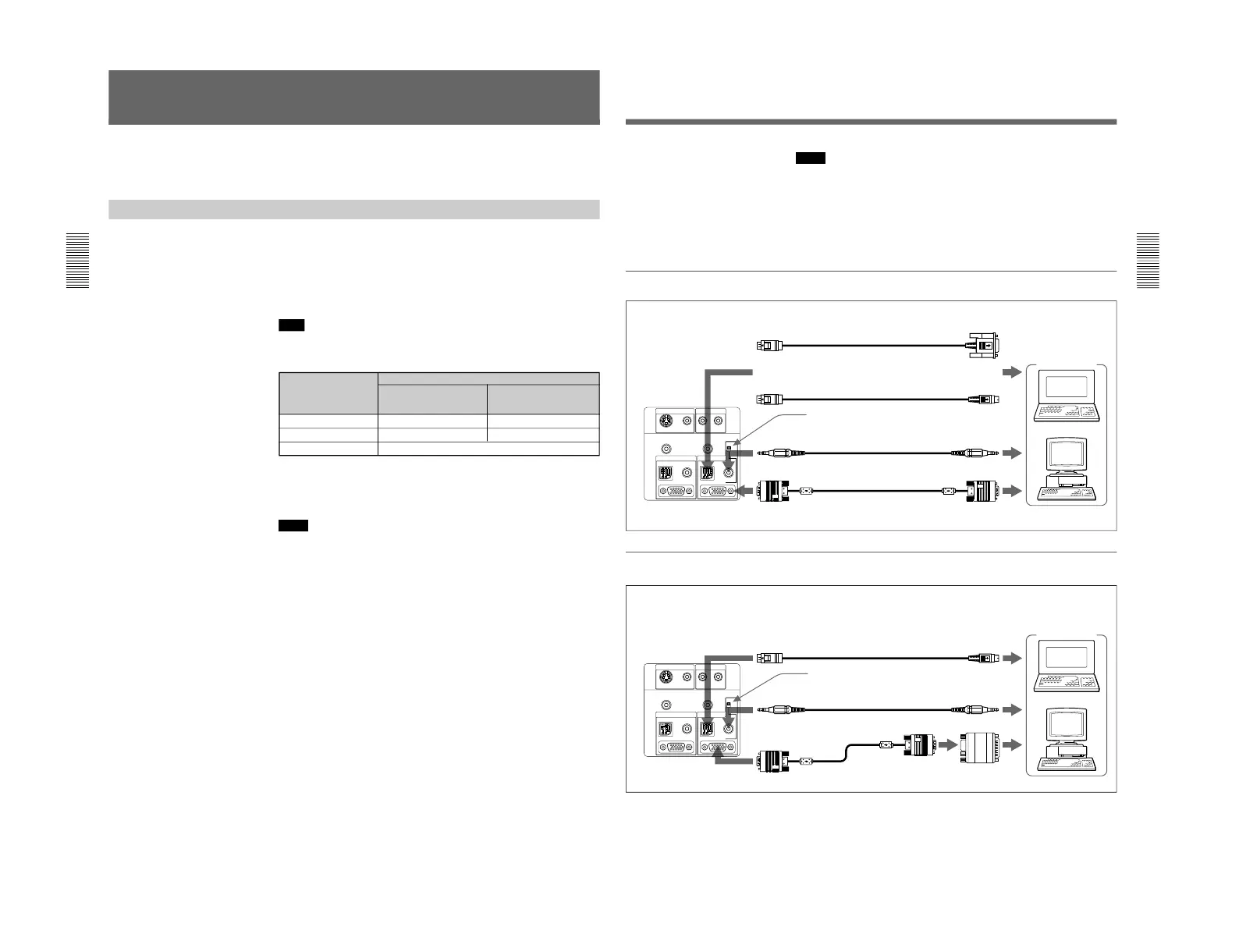
When connecting with an IBM PC/AT compatible computer
When connecting with a Macintosh computer
Computer
Rear
to INPUT A or
INPUT B
SIC-S21 Mouse cable for serial port (supplied)
to serial port
to mouse port
SIC-S22 Mouse cable for PS/2 port (supplied)
to audio out
Stereo audio connecting
cable (not supplied)
to monitor out
Rear
to INPUT A or
INPUT B
SIC-S20 Mouse cable (supplied)
to mouse port
to audio out
Stereo audio connecting
cable (not supplied)
to monitor out
SMF-401 HD D-sub 15-
pin cable (supplied)
Signal adapter
(supplied)
For details on the DIP switch setting of the adapter, see page 43 (EN).
Notes
•Connect all the connecting cables to the INPUT A connector when you
input a signal from the INPUT A connector.
Connect all the cables to the INPUT B connector when you input a signal
from the INPUT B connector as well.
•When connecting to INPUT B, make sure that the RGB IN/OUT select
switch is set to IN.
•Supplied mouse cable may not work properly according to your
computer.
or
Computer
SMF-401 HD D-sub 15-pin
cable (supplied)
Set this switch to IN.
Set this switch to IN.
 Loading...