3
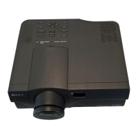
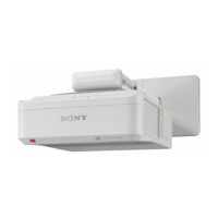
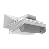
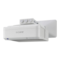
VPL-S900E, VPL-S900M, VPL-S900U
TABLE OF CONTENTS
1. OPERATING INSTRUCTIONS
1-1. VPL-S900U/S900E/S900M OPERATING INSTRUCTIONS ...................... 1-1
1-2. VPL-S900U/S900E/S900M INSTALLATION MANUAL
FOR DEALERS ........................................................................................... 1-25
1-3. IFB-X600E OPERATING INSTRUCTIONS.............................................. 1-37
1-4. PSS-600 INSTALLATION MANUAL ....................................................... 1-40
2. SERVICE INFORMATIONS
2-1. CIRCUIT BOARDS LOCATIONS ............................................................... 2-1
2-2. DISASSEMBLY ............................................................................................ 2-2
2-2-1. Cabinet Assy Removal ........................................................................... 2-2
2-2-2. Front Panel Assy and NF Board Removal ............................................. 2-2
2-2-3. Scan Converter Unit Removal ................................................................ 2-2
2-2-4. GA and U Boards Removal .................................................................... 2-2
2-2-5. Power Supply Block Removal................................................................ 2-3
2-2-6. F Board Removal.................................................................................... 2-3
2-2-7. Connector Panel Assy, QA, QB, QC, QD and NR Boards Removal ..... 2-3
2-2-8. C Board Removal ................................................................................... 2-4
2-2-9. Optical Unit Removal ............................................................................. 2-4
2-2-10. GB, GBA and V Boards Removal.......................................................... 2-4
2-2-11. BA and BAA Boards Removal............................................................... 2-4
2-2-12. Lens Removal ......................................................................................... 2-5
2-2-13. Lens Adjustment..................................................................................... 2-5
2-2-14. Prism Block and Condenser Lens Removal ........................................... 2-5
2-2-15. Condenser Lens Adjustment................................................................... 2-5
3. ADJUSTMENTS
3-1. VCOM ADJUSTMENT ................................................................................. 3-1
3-2. Signal Level Adjustment ................................................................................ 3-1
3-2-1. RGB Level Adjustment .......................................................................... 3-1
3-2-2. VIDEO Level Adjustment ...................................................................... 3-1
3-2-3. Adjustment of VIDEO SUB HUE and COLOR .................................... 3-2
3-3. X1000&S900 SERIES MEMORY STRUCTURE ........................................ 3-3
4. SEMICONDUCTORS
5. EXPLODED VIEWS
5-1. CABINET BLOCK ........................................................................................ 5-2
5-2. CHASSIS BLOCK......................................................................................... 5-3
5-3. BASE BLOCK ............................................................................................... 5-4
5-4. OPTICAL UNIT BLOCK .............................................................................. 5-5
6. ELECTRICAL PARTS LIST
7. BLOCK DIAGRAMS
7-1. BA, QB BOARD BLOCK DIAGRAM .......................................................... 7-1
7-2. BB BOARD BLOCK DIAGRAM (1/2) ......................................................... 7-2