2-4
VPL-S900E, VPL-S900M, VPL-S900U
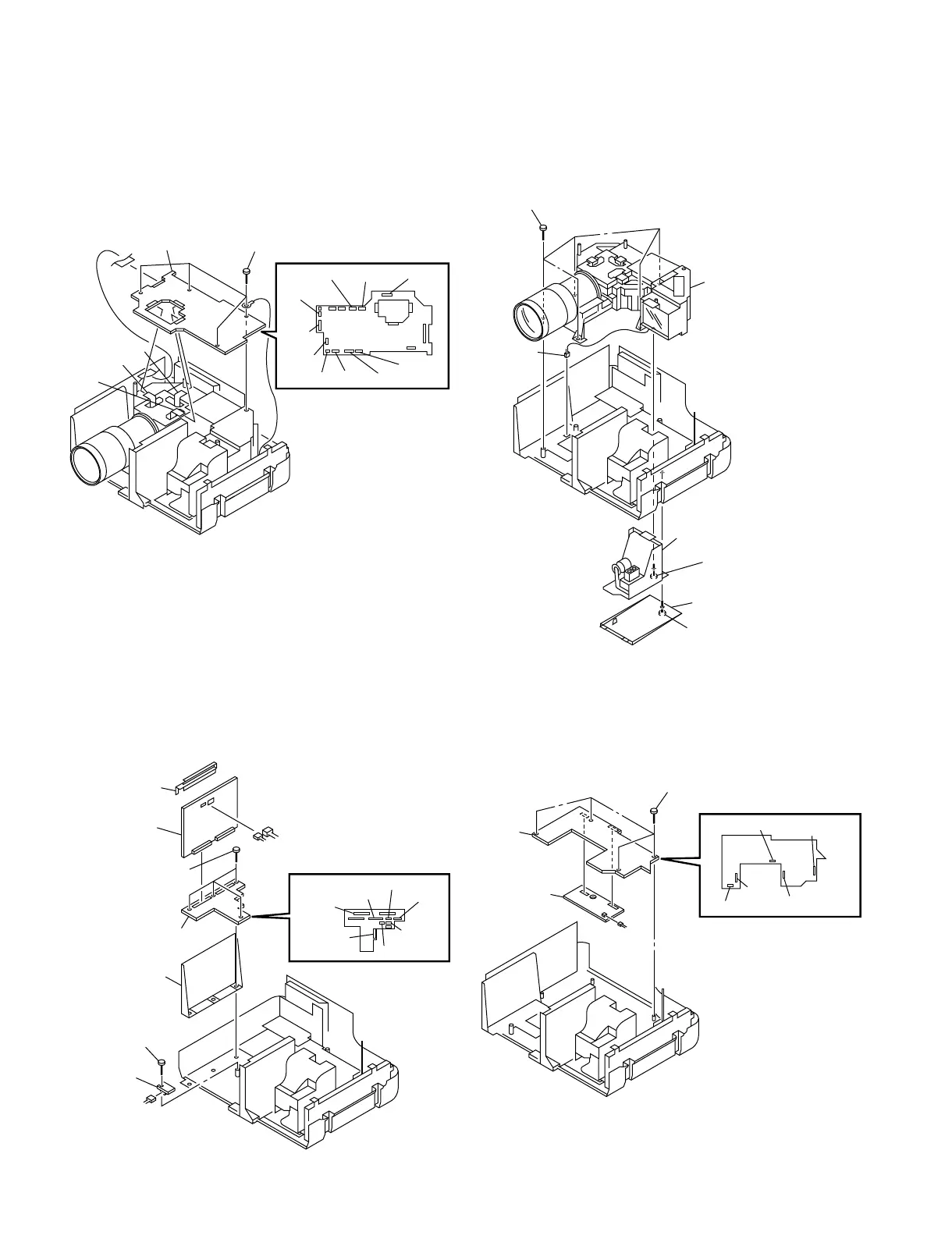
2-2-8. C Board Removal 2-2-9. Optical Unit Removal
2-2-10. GB, GBA and V Boards Removal 2-2-11. BA and BAA Boards Removal
• Remove the connector panel assy (Refer to 2-2-7.)
• Remove the C board (Refer to 2-2-8.)
• Remove the optical unit (Refer to 2-2-9.)
• Remove the scan converter unit (Refer to 2-2-3.)
• Remove the C board (Refer to 2-2-8.)
• Remove the optical unit (Refer to 2-2-9.)
• Remove the C board (Refer to 2-2-8.)
1 Four screws
(+PSW 3 × 8)
2 C board
CN5008
CN5202
CN5304
CN5303
CN5003
CN5006
CN5020
CN5022
CN5012
CN5001
CN5002
CN5101
CN5023
CN5007
5 Five screws
(+PSW 4 × 12)
6 Optical unit
CN7110
4 Lamp
2 Lamp cover
1 Screw
(+B 3 × 10)
3 Screw
(Prevention
screw +B 3 × 12)
1 GB holder (TP)
2 GB board
3 Four screws
(+PSW 3 × 8)
CN7001
CN7105
CN7103
CN7104
CN7106
CN7108
CN7101
CN7107
CN7002
4 GBA board
5 GB holder
6 Screw
(+PSW 3 × 8)
7 V board
CN4201
1 Four screws
(+PSW 3 × 8)
2 BA board
3 BAA board
CN2802
CN2003
CN2004
CN2007
CN2005
CN2006



 To Next Page