EasyManua.ls Logo

Sony WM-EX422 User Manual

Sony WM-EX422
18 pages
To Next Page IconTo Next Page
Page #1 background imageLoading...
Page #1 background image
WM-EX422
SERVICE MANUAL
SPECIFICATIONS
E Model
Model Name Using Similar Mechanism NEW
MD Mechanism Type MF-WMFX495-147
9-877-095-02
2003L02-1
© 2003.12
Sony Corporation
Personal Audio Company
Published by Sony Engineering Corporation
CASSETTE PLAYER
Ver 1.1 2003.12
• Frequency response
Playback: 30 - 18 000 Hz
• Output
Headphones (i) jack Load impedance 8 - 300
• Power requirements
1.5V DC, battery R6 (AA) x 1
• Dimensions (w/h/d)
Approx. 111.2 x 81.1 x 29.5 mm (4
1
2
x 3
1
4
x1
3
16
in.), excl.
projecting parts and controls
• Mass
Approx. 124 g (4.4 oz) (main unit only)
• Supplied accessories
Stereo headphones or earphones (1)
Hand strap (1) (European model only)
Carrying pouch (1) (Asian model only)
Design and specifications are subject to change without notice.
Battery life* (approximate hours)
Sony alkaline LR6 (SG)** Sony R6P (SR)
Tape playback 35 9
* Measured value by the standard of JEITA (Japan Electronics and
Information Technology Industries Association).
(Using a Sony HF series cassette tape)
**When using a Sony LR6(SG) “STAMINA” alkaline dry battery
(produced in Japan).
Note
• The battery life may be shorter depending on the operating condition, the
surrounding temperature and battery type.
Question and Answer IconNeed help?

Do you have a question about the Sony WM-EX422 and is the answer not in the manual?
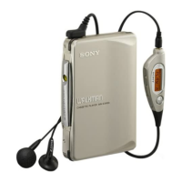
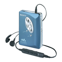
Sony WM-EX422 Specifications

General IconGeneral
TypeCassette Player
BrandSony
ModelWM-EX422
Power Supply2 x AA batteries
Battery LifeApprox. 24 hours
HeadphonesIncluded
FeaturesMega Bass
Frequency Response40 - 15, 000 Hz

Summary

Servicing Notes and Procedures

Setting Up for Servicing

Procedures for setting up the device for maintenance checks, including board connection and power supply.

Preset State Adjustment

Steps to set the internal mechanisms to a specific state for calibration and testing.

FF and REW Mode Operation

Instructions for verifying Fast Forward and Rewind modes using signal inputs.

PLAY Mode Operation

Procedure for setting and verifying the PLAY mode using signal inputs and mechanism feedback.

Disassembly Procedures

Cabinet (Front) Sub Assembly Removal

Step-by-step guide to removing the front cabinet parts and related components.

Main Board Removal

Instructions on how to safely detach and remove the main circuit board.

Mechanism Deck Removal

Detailed steps for disassembling and removing the tape mechanism deck.

Cassette Holder Sub Assembly Removal

Procedure for removing the cassette holder and associated parts, including springs.

Adjustments and Calibration

Mechanical Adjustments

Procedures for mechanical adjustments, including torque measurements for various tape transport modes.

Electrical Adjustments

Steps for electrical calibration, focusing on tape speed adjustment using test tapes and frequency counters.

Circuit Diagrams and Boards

Block Diagrams

Overview of the device's functional blocks and signal flow.

Printed Wiring Boards

Layout diagrams showing component placement and traces for both sides of the main board.

Schematic Diagram

Detailed electronic schematic showing circuit connections and component values.

IC Block Diagrams

Internal block diagrams for key integrated circuits (ICs) used in the device.

Exploded Views and Parts

Cabinet Section Exploded View

Visual breakdown of the cabinet assembly, showing all external and internal cabinet parts.

Mechanism Deck Section Exploded View

Visual breakdown of the tape mechanism, detailing all gears, levers, and motor components.

Electrical Parts List

Revision History

Related product manuals