WM-EX527
1616
1
2
3
5
4
CHIP ENABLE
SLOW START
PHASE COMP
VLX LIMITER
PWM CONTROL
OSC 50/100/180kHz
+
–
NC
VOUT
CE
VDD
VSS
LX
VREF
BUFFER
ERROR
AMP
V
1
PW
2
W
3
GND
4
OSC
5
DR
6
VREF
7
START
8
VSP
9
IN+
10
PV
20
U
19
PU
18
GND
17
VCC
16
FC
15
TC1
14
TC2
13
R1
12
OUT
11
MOTIVE
CONTROL
CIRCUIT
MOTIVE/
OSC
MOTIVE
LOGIC
SOFT SWITCH
PRE DRIVER
INVERTER
BIAS
REFERENCE
VOLTAGE
SPEED
CONTROL
CURRENT
CONTROL
OUTPUT
BIAS
+
–
PRE A
PRE B
MIX
PW B
PW A
PW C
BST
MT TC
BASE
RF IN
PW GND
OUT B
OUT C
OUT A
VCC
RF OUT
VREF OUT
BST NF
BST OUT
PW IN C
LPF
EQ A
PW NF A
PW IN A
PW IN B
PW NF B
3
IN A-R
5
PRE NF-A
6
PRE OUT A
7
MTL DRV A
8
MTL DRV B
9
PRE OUT B
10
PRE NF-B
11
AMS IN
12
IN B-R
4
IN B-F
2
IN A-F
1
21
20
19
18
17
GND
16
AMS DET
15
AMS MIX
14
AMS SW
13
22
23
24
38
C-AMP SW
37
PW SW
42
MT SW
41
F/R SW
44
BST SW
43
M/N SW
46
PRE GND
47
VREF IN
48
PRE SW
45
AMS OUT
40
BEEP
39
262728293031323334
DET
36
AGC IN
35
+
–
+
–
+
–
+
–
+
–
+
–
EQ B
25
RIPPLE
FILTER
AGC
DET
BEEP
VREF
SWITCH
COMPARATOR
MTL DRV
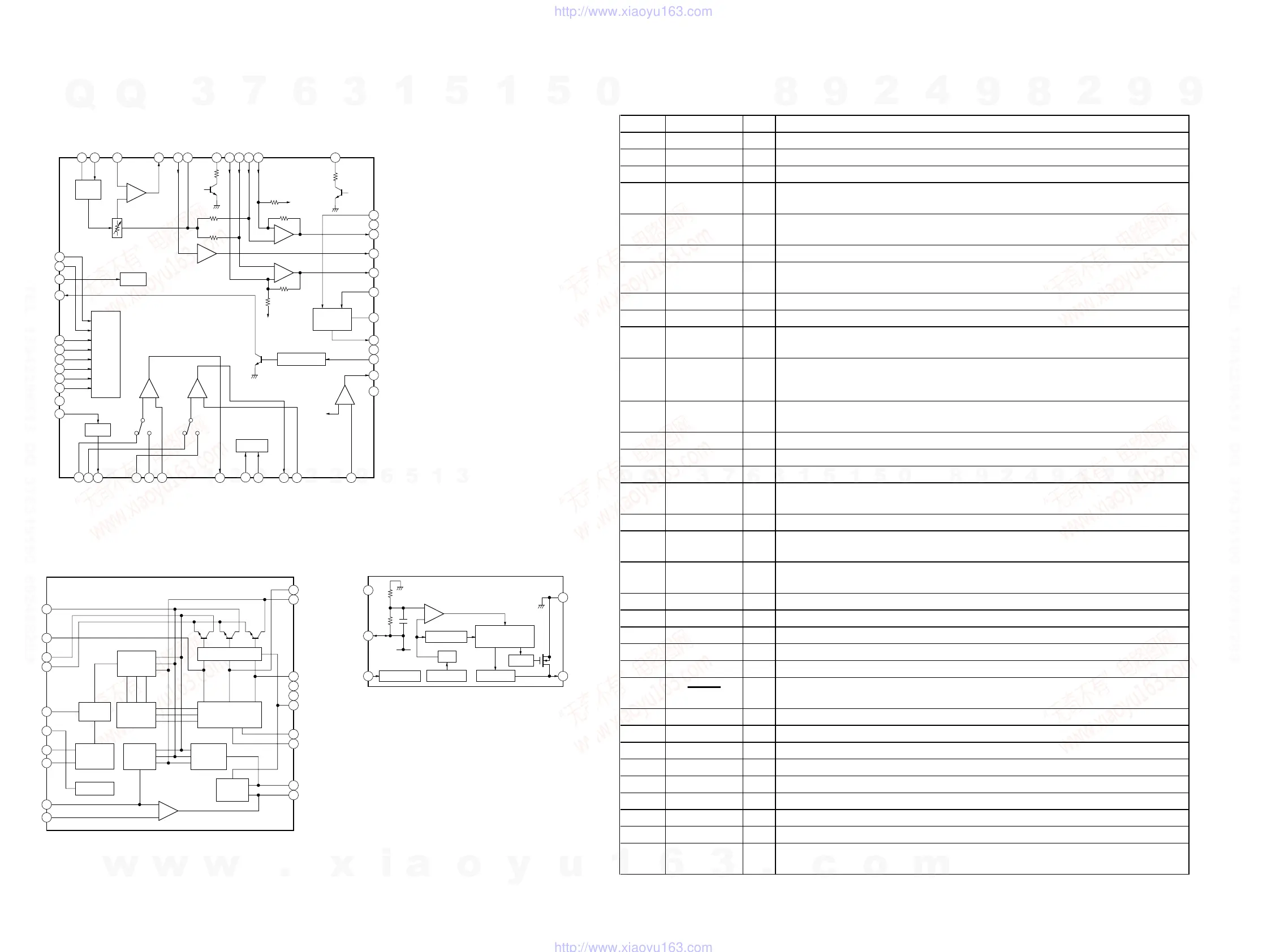
• IC Block Diagrams
IC301 TA2123AF (EL)
IC601 MM1279XVBE IC702 XC6371C251PL
6-5. IC PIN FUNCTION DESCRIPTION
• IC701 uPD789166GB-510-8ES (SYSTEM CONTROLLER)
Pin No. Pin Name I/O Description
1BATT DET I Battery voltage detection signal input (A/D input)
2 KEY IN I Key input terminal (A/D input)
3 F/R SW I Tape direction switch input terminal “L”: forward position
4AMS IN I
Whether a music is present or not from the audio master amp is detected at auto music sensor
“L”: music is present
5OSC IN I
Motor restart control signal input from the capstan/reel motor drive
“H”: FF/REW motor rotation status
6NCINot used
7
DOLBY KEY
CTL
I
Dolby is present or not control signal input terminal
“H”: Dolby is present (fixed at “L” in this set)
8 PHOTO IN I Rotation detect signal input of the capstan/reel motor
9AVSS — Ground terminal (for A/D converter)
10 PHOTO CTL O
Control signal output to the capstan/reel motor rotation detect circuit
“L”: rotation detect circuit on
11 AMP CTL O
Also, this is used as control signal output for power on/off to the audio master amplifier, or power
supply output for the Dolby NR amplifier “H”: power on
Dolby NR amplifier: Not used in this set
12 WAKE UP I
Input of acknowledge signal for the key entry Acknowledge signal is input to accept function in
the power off status On at input of “H”
13 TAPE SW I Cassette tape detect switch input terminal “L”: cassette detected
14 RMUM I Connection detection signal input of the remote commander
15 BEEP O Beep sound signal output to the audio master amplifier
16 F/R CTL O
Forward/reverse selection signal output to the audio master amplifier
“L”: forward direction, “H”: reverse direction
17 VDD1 — Power supply terminal (+2.5V)
18 AVLS CTL O
AVLS (Automatic Volume Limiter System) on/off control signal output
“H”: AVLS on
19 GRV/MB CTL O
Emphasizing sound control signal output to the audio master amplifier
“L”: MB (mega bass), “H”: normal/GRV (groove)
20 BST CTL O Bass boost control signal output to the audio master amplifier “H”: bass boost on
21 LED DOLBY O LED drive signal output of the Dolby NR indicator “L”: LED on Not used
22 IC0 — Not used
23 XT2
O
Sub clock output terminal Not used
24 XT1 I Sub clock input terminal Not used
25
RESET I
System reset signal input from the reset signal generator “L”: reset
“L” is input for several 100 msec after power on, then it changes to “H”
26 X2 O System clock output terminal (4 MHz)
27 X1 I System clock input terminal (4 MHz)
28 VSS0 — Ground terminal
29 VDD0 — Power supply terminal (+2.5V)
30 R DATA OUT O Communication serial data output to the remote commander
31 LED BATT O LED drive signal output of the BATT indicator “H”: LED on
32 DOLBY CTL O Dolby on/off control signal output to the Dolby NR amplifier “L”: Dolby NR on Not used
33 MOTOR CTL O Motor start control signal output to the capstan/reel motor drive “H”: motor on
34 MOTOR DIR O
Motor direction control signal output to the capstan/reel motor drive
“L”: counterclockwise, “H”: clockwise
w
w
w
.
x
i
a
o
y
u
1
6
3
.
c
o
m
Q
Q
3
7
6
3
1
5
1
5
0
9
9
2
8
9
4
2
9
8
T
E
L
1
3
9
4
2
2
9
6
5
1
3
9
9
2
8
9
4
2
9
8
0
5
1
5
1
3
6
7
3
Q
Q
TEL 13942296513 QQ 376315150 892498299
TEL 13942296513 QQ 376315150 892498299
http://www.xiaoyu163.com
http://www.xiaoyu163.com
 Loading...